Restraint Control Module (Remove and Install)
 Correction code
2020010301
FRT
1.32
NOTE: Unless otherwise explicitly stated in the procedure, the correction code and FRT listed above reflect all of the work required to perform this procedure, including the linked procedures. Do not stack correction codes unless explicitly told to do so.
NOTE: See Flat Rate Times to learn more about FRTs and how they are created.
NOTE: See Personal Protection to make sure you
are wearing proper PPE when performing the procedure below.
NOTE: See Ergonomic Precautions for safe and healthy working practices.
Correction code
2020010301
FRT
1.32
NOTE: Unless otherwise explicitly stated in the procedure, the correction code and FRT listed above reflect all of the work required to perform this procedure, including the linked procedures. Do not stack correction codes unless explicitly told to do so.
NOTE: See Flat Rate Times to learn more about FRTs and how they are created.
NOTE: See Personal Protection to make sure you
are wearing proper PPE when performing the procedure below.
NOTE: See Ergonomic Precautions for safe and healthy working practices.
- 2026-01-27: Added steps to disarm and re-arm the RCM.
Torque Specifications
| Description | Torque Value | Recommended Tools | Reuse/Replace | Notes |
|---|---|---|---|---|
| Nuts (x3) that attach the restraint control module to the body |
 10 Nm (7.4 lbs-ft) |
|
Replace | 1004378-00-B |
Remove
- Enable Service Mode Plus. See Service Mode Plus
-
On the touchscreen, touch , touch Run, and allow the routine to complete.
NoteMake sure that airbags are disarmed after the routine has completed.
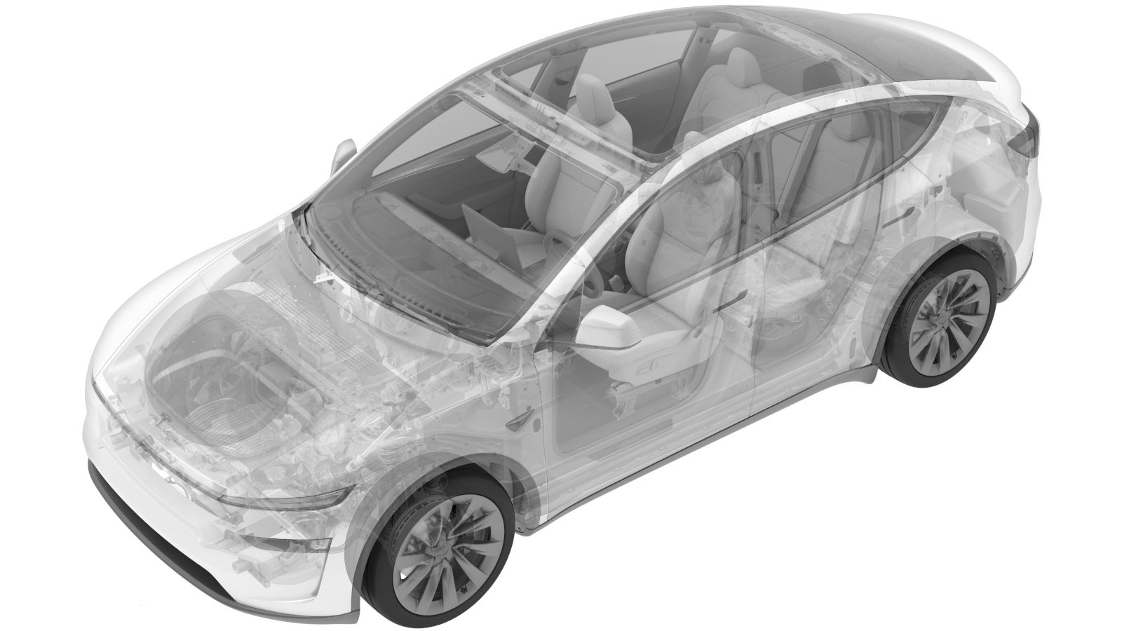
Model Y shown, other models similar
- Exit Service Mode Plus. See Service Mode Plus
- Remove the 1st row podium. See 1st Row Podium (Remove and Replace).
-
Disengage the locking levers, and then
disconnect the electrical connectors (x2) from the restraint control module.
WarningMake sure LV power has been disconnected for at least 2 minutes before disconnecting the electrical harness from the restraint control module. Failure to do so can result in unintended safety system behaviors.
-
Remove and discard the nuts (x3) that attach the restraint control module to the body, and then remove the module from the vehicle.
NoteUse of the following tool(s) is recommended:
- 10 mm socket
Install
-
Install the restraint control module
to the body, and then install new nuts (x3) to attach the module to the body.10 Nm (7.4 lbs-ft)NoteUse of the following tool(s) is recommended:
- 10 mm socket
-
Connect the electrical connectors (x2)
to the restraint control module and then engage the connector locking levers.
- Install the 1st row podium. See 1st Row Podium (Remove and Replace).
- Enable Service Mode Plus. See Service Mode Plus
-
On the touchscreen, touch , touch Run, and allow the routine to
complete.
NoteMake sure the airbags are armed after the routine has completed.
- Exit Service Mode Plus. See Service Mode Plus