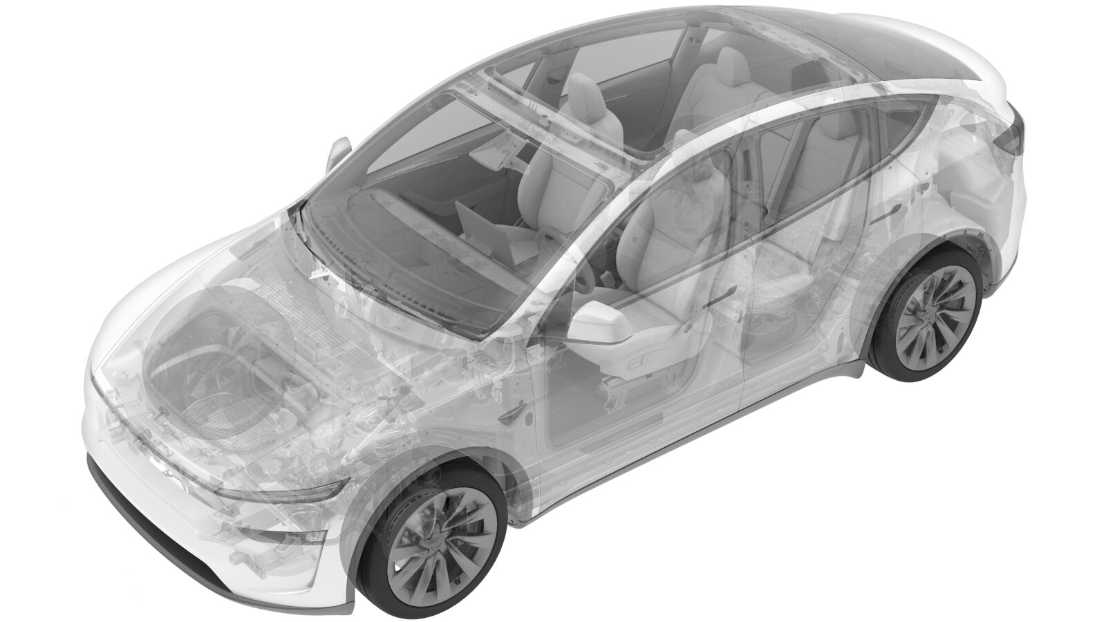
Power Conversion System (Remove and Install)
 Correction code
1630010251
FRT
2.34
NOTE: Unless
otherwise explicitly stated in the procedure, the above correction code and
FRT reflect all of the work required to perform this procedure, including
the linked procedures. Do
not stack correction codes unless explicitly told to do so.
NOTE: See Flat Rate
Times to learn more about FRTs and how
they are created. To provide feedback on FRT values, email ServiceManualFeedback@tesla.com.
NOTE: See Personal Protection
to make sure wearing proper PPE when performing the below procedure.
NOTE: See Ergonomic Precautions for safe and
healthy working practices.
- 2025-12-25: Added a note to lubricate the O-ring with Krytox 203.
- 2025-11-13: Add a step of ancillary bay leak test.
Torque Specifications
| Description | Torque Value | Recommended Tools | Reuse/Replace | Notes |
|---|---|---|---|---|
| Bolts (x3) securing PCS to HV battery |
 18 Nm (13.3 lbs-ft) |
|
Reuse | Ensure only the 8mm fasteners are removed, Do not remove the T30 fasteners. |
Remove
- On the touchscreen, tap the Service Mode "wrench" (at the bottom of the touchscreen UI), and then tap , and allow the routine to complete.
- Perform penthouse coolant drain. See Ancillary Bay Coolant (Drain And Refill) (Test/Adjust).
- Remove HV controller and hinge tray from penthouse assembly. See HV Controller (Remove and Install).
- Position absorbent sheets below and around PCS coolant inlet hose to avoid excess coolant dripping.
-
Disconnect PCS coolant inlet hose from
PCS.
-
Disconnect PCS coolant outlet hose
from PCS.
-
Disconnect PCS to DC bus HV
connector.
-
Disconnect PCS logic connector from
PCS.
-
Disconnect PCS LV connector from
PCS.
-
Disconnect AC harness connector from
PCS.
-
Remove bolts securing PCS to HV
battery.
TIpUse of the following tool(s) is recommended:
- 8 mm socket
- Class 0 Electrical Protective Gloves
- Insulated Ratchet/torque wrench
- Flex head ratchet/flex head torque wrench
-
Secure suction cups to PCS.
-
Lift PCS up and out of ancillary bay
area and remove from vehicle.
Install
-
Position PCS into ancillary bay.
-
Remove suction cups from PCS.
-
Install bolts securing PCS to HV
battery.
 18 Nm (13.3 lbs-ft)TIpUse of the following tool(s) is recommended:
- 8 mm socket
- Class 0 Electrical Protective Gloves
- Insulated Ratchet/torque wrench
- Flex head ratchet/flex head torque wrench
-
Connect AC harness connector to
PCS.
-
Connect PCS LV connector to PCS.
-
Connect PCS logic connector to
PCS.
-
Connect PCS to DC bus HV
connector.
-
Connect PCS coolant inlet hose to
PCS.
-
Replace O-ring on PCS side outlet
hose.
NoteApply light amount of Krytox 203 to lubricate the O-ring.
-
Connect PCS coolant outlet hose to
PCS.
- Install HV controller and hinge tray to penthouse assembly. See HV Controller (Remove and Install).
- Install the pyrotechnic battery disconnect. See Pyro Disconnect - HV Battery (Remove and Replace).
- Perform the penthouse coolant refill. See Ancillary Bay Coolant (Drain And Refill) (Test/Adjust).
- Connect the LV power. See LV Power (Disconnect and Connect) (Modify).
- Select , and allow the routine to complete.
-
Select , and allow the routine to complete.
NoteMake sure vehicle is not in Drive, shifting the vehicle into Drive will stop this routine. The test will last approximately 10 mins. The test will vary speeds from 3500-6500 RPM (idle speed = ~1500 RPM) and actuate the valve between series and parallel. If speed hovers at 7000 RPM, it indicates the pump is air locked, perform the vacuum fill again. Continue to add coolant and purge until the coolant level reaches between the NOM and MAX Lines on the bottle.
- Install the ancillary bay cover. See Cover - Ancillary Bay (Remove and Replace).
-
Perform the ancillary bay leak test. See Ancillary Bay Air Leak Test (Inspection).
NoteOnly when the cover seal is damaged, and new one is installed.