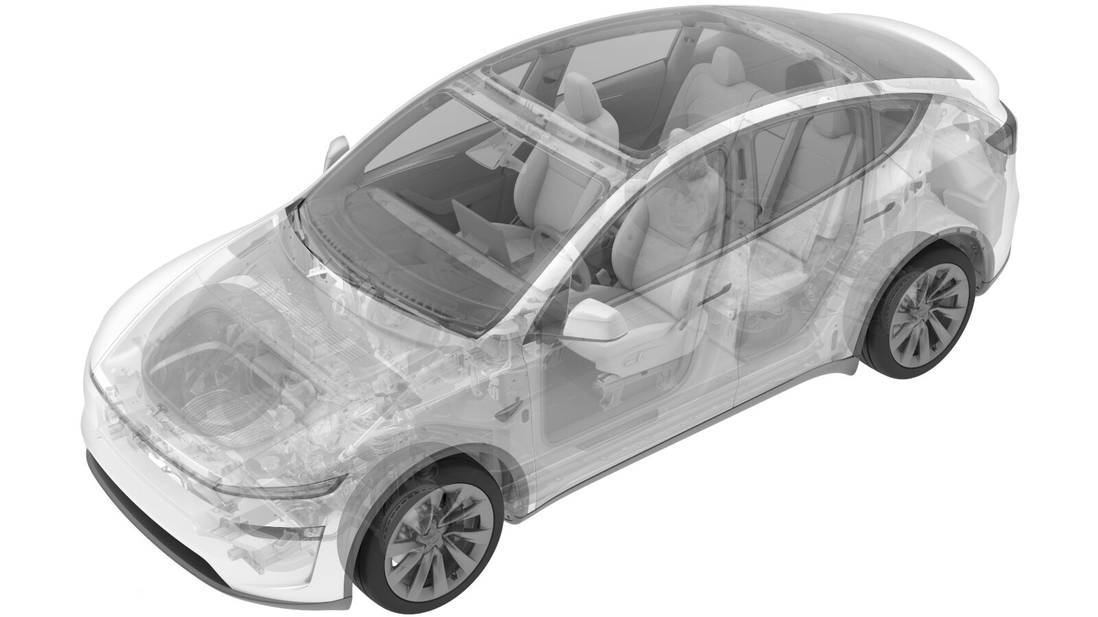
LHD Mount - 4DU (Remove and Install)
 Correction code
4001010601
FRT
1.80
NOTE: Unless
otherwise explicitly stated in the procedure, the above correction code and
FRT reflect all of the work required to perform this procedure, including
the linked procedures. Do
not stack correction codes unless explicitly told to do so.
NOTE: See Flat Rate
Times to learn more about FRTs and how
they are created. To provide feedback on FRT values, email ServiceManualFeedback@tesla.com.
NOTE: See Personal Protection
to make sure wearing proper PPE when performing the below procedure.
NOTE: See Ergonomic Precautions for safe and
healthy working practices.
Torque Specifications
| Description | Torque Value | Recommended Tools | Reuse/Replace | Notes |
|---|---|---|---|---|
| LH mount bolt (X1) securing drive unit to subframe |
 80 Nm (59.0 lbs-ft) |
|
Reuse | Use a pry to aid as needed, do not damage drive unit casting |
| Bolts (X3) securing LH mount assembly to RDU |
 35 Nm (25.8 lbs-ft) +55 degree |
|
Replace |
Remove
- Partially lower the rear subframe and drive unit assembly. See Rear Subframe (Remove and Replace)
-
Support center of the rear drive unit with protective block.
-
Remove LH mount bolt securing drive unit to subframe.
TIpUse of the following tool(s) is recommended:
- 18 mm socket
- Cordless Ratchet/Impact Driver
-
Remove bolts securing LH mount assembly to rear drive unit.
TIpUse of the following tool(s) is recommended:
- External Torx E14
- Cordless Ratchet/Impact Driver
-
Release inverter to oil cooler hose from in between LH motor mount.
NotePlugs ends as needed, release clip from in between mount and NVH cover, completely release the clip.
-
Remove LH mount assembly from between rear drive unit and subframe.
Install
-
Position LH mount assembly in between
rear drive unit and subframe.
-
Remove plugs and secure inverter to cooler hose to inverter.
-
Install bolts securing LH mount assembly to rear drive unit.
 35 Nm (25.8 lbs-ft) +55 degreeTIpUse of the following tool(s) is recommended:
- External Torx E14
- Cordless Ratchet/Impact Driver
-
Install LH bolt securing rear drive unit to subframe.
 80 Nm (59.0 lbs-ft)TIpUse of the following tool(s) is recommended:
- 18 mm socket
- Cordless Ratchet/Impact Driver
-
Remove center support from rear drive unit.
- Install the rear subframe and drive unit assembly. See Rear Subframe (Remove and Replace)