2026-07-24
Steering Gear - LHD (Remove and Replace)
 Correction code
3201010202
FRT
0.90
NOTE: Unless otherwise explicitly stated in the procedure, the correction code and FRT listed above reflect all of the work required to perform this procedure, including the linked procedures. Do not stack correction codes unless explicitly told to do so.
NOTE: See Flat Rate Times to learn more about FRTs and how they are created.
NOTE: See Personal Protection to make sure you
are wearing proper PPE when performing the procedure below.
NOTE: See Ergonomic Precautions for safe and healthy working practices.
Correction code
3201010202
FRT
0.90
NOTE: Unless otherwise explicitly stated in the procedure, the correction code and FRT listed above reflect all of the work required to perform this procedure, including the linked procedures. Do not stack correction codes unless explicitly told to do so.
NOTE: See Flat Rate Times to learn more about FRTs and how they are created.
NOTE: See Personal Protection to make sure you
are wearing proper PPE when performing the procedure below.
NOTE: See Ergonomic Precautions for safe and healthy working practices.
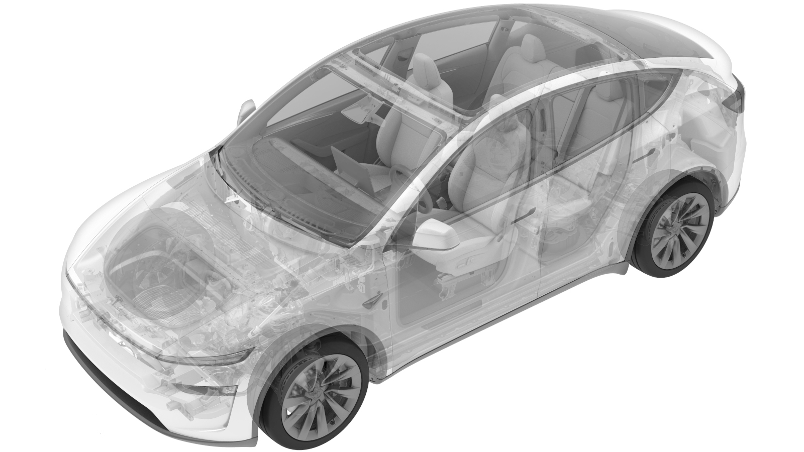
- 2026-07-24: Added an animation to better illustrate steering gear removal.
Torque Specifications
| Description | Torque Value | Recommended Tools | Reuse/Replace | Notes |
|---|---|---|---|---|
| Bolts (x2) that attach the underhood storage unit reinforcement bracket to the cooling fan |
 46.5 Nm (34.3 lbs-ft) |
|
Reuse | |
| Bolts (x2) that attach the cooling fan assembly to the front end module |
6 Nm (4.4 lbs-ft) |
|
Reuse | |
| Bolt that attach the steering column to the steering gear assembly |
18 Nm (13.3 lbs-ft) |
|
Replace | 1111523-00-A |
| Inner bolts (x2) that attach the steering gear assembly to the front subframe |
75 Nm (55.3 lbs-ft) |
|
Reuse | |
| Outer bolts (x2) that attach the steering gear assembly to the front subframe |
47 Nm (34.7 lbs-ft) |
|
Reuse | |
| Jamb nuts (x2) that attache the outer tie rod ends to the inner tie rod ends |
80 Nm (59.0 lbs-ft) |
|
Reuse |
Remove
-
Remove the steering gear. See Steering Gear - LHD (Remove and Install).
Install
-
Mark the threads on the LH inner tie
rod and nut on the new steering gear assembly using a paint pen.
-
Loosen the jamb nut on the LH outer
tie rod, and then turn the outer tie rod end counterclockwise to remove tie rod end from
the new steering gear assembly.
TIpUse of the following tool(s) is recommended:
- 21 mm 12pt combination wrench
-
Turn the steering rack assembly fully
to the right using a wrench.
-
Install the new steering gear assembly
into the vehicle.
CAUTIONDo not damage other components.NoteInstall the steering gear assembly through the underhood storage unit opening. Install the RH side of the steering gear assembly into frunk area first, and then slide the LH side of the steering gear assembly into the vehicle.
-
Loosely install the outer bolts (x2)
that attach the steering gear assembly to the front subframe.
NoteTorque at a later step.
-
Loosely install the inner bolts (x2)
that attach the steering gear assembly to the front subframe.
NoteTorque at a later step.
-
Torque the inner bolts (x2) that
attach the steering gear assembly to the front subframe.75 Nm (55.3 lbs-ft)TIpUse of the following tool(s) is recommended:
- 18 mm socket
-
Torque the outer bolts (x2) that
attach the steering gear assembly to the front subframe.47 Nm (34.7 lbs-ft)TIpUse of the following tool(s) is recommended:
- 15 mm socket
-
Install the clip that attaches the
steering gear harness to the front subframe.
-
Connect the steering gear assembly
connectors (x4).
-
Slide the electric steering column
downward to install it to the steering gear assembly.
- Install the clip that attaches the radiator inlet hose to the front rail harness bracket.
-
Install a new bolt that attaches the
steering column to the steering gear assembly.18 Nm (13.3 lbs-ft)TIpUse of the following tool(s) is recommended:
- 13 mm deep socket
-
Release the bungee cord to place the
radiator assembly back to the normal position.
-
Install the bolts (x2) that attach the
cooling fan assembly to the front end module.6 Nm (4.4 lbs-ft)TIpUse of the following tool(s) is recommended:
- 8 mm socket
-
Position the underhood storage unit
reinforcement bracket to the cooling fan, and then install the bolts (x2) that attach
the underhood storage unit reinforcement bracket to the cooling fan.46.5 Nm (34.3 lbs-ft)TIpUse of the following tool(s) is recommended:
- External Torx Plus EP14
-
Install the clips (x3) that attach the
steering gear harness to the underhood storage unit reinforcement bracket.
- Install the underhood storage unit. See Underhood Storage Unit (Remove and Replace).
- Connect the LV power. See LV Power (Disconnect and Connect) (Modify).
- Remove the steering wheel holder.
- Turn the steering wheel to the center position.
- Enable Service Mode. See Service Mode.
- On the vehicle touchscreen, touch and verify that the steering wheel is approximately at 0 degrees.
- Reinstall the vehicle software. See Software Reinstall - Touchscreen
- Install the LH and RH tie rods. See Tie Rod Outer - LH (Remove and Replace).
- Refer to the Alignment Requirement tables to determine whether an EPAS alignment check (EC) or four wheel alignment check (AC) is necessary. If performed, add the alignment check/adjust as a separate activity. See Alignment Requirement - Suspension.