Brake Lines - Rear Brake Pipe - RH (Remove and Replace)
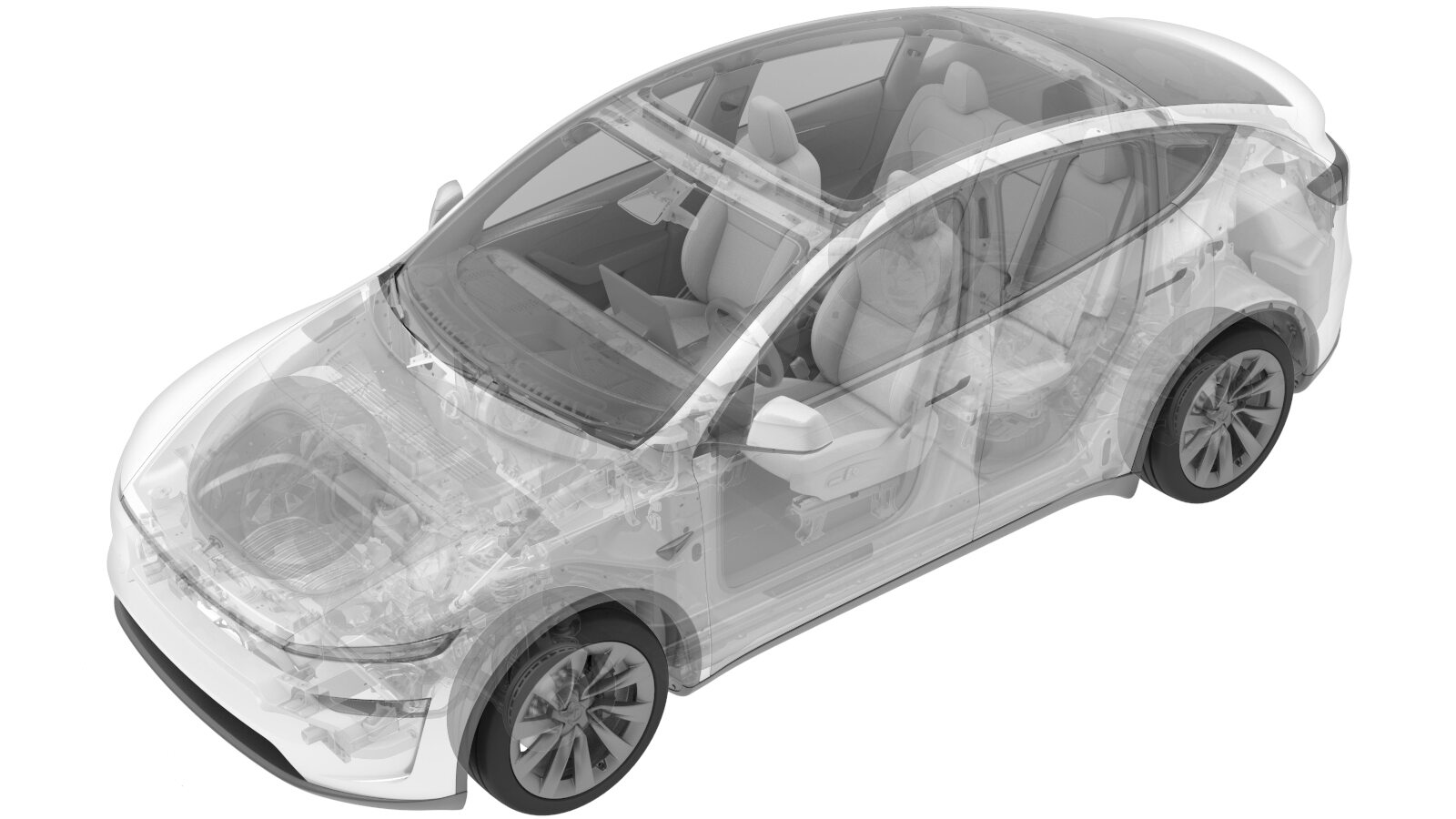 Correction code
3303010802
FRT
2.70
NOTE: Unless
otherwise explicitly stated in the procedure, the correction code and its
associated FRT reflect all of the work required to perform this procedure,
including the linked procedures. Do not stack correction
codes unless explicitly told to do so.
NOTE: See Flat Rate Times to
learn more about FRTs and how they are created.
NOTE: See Personal Protection to make
sure you are wearing proper PPE when performing the procedure below.
NOTE: See Ergonomic Precautions for safe and healthy
working practices.
Correction code
3303010802
FRT
2.70
NOTE: Unless
otherwise explicitly stated in the procedure, the correction code and its
associated FRT reflect all of the work required to perform this procedure,
including the linked procedures. Do not stack correction
codes unless explicitly told to do so.
NOTE: See Flat Rate Times to
learn more about FRTs and how they are created.
NOTE: See Personal Protection to make
sure you are wearing proper PPE when performing the procedure below.
NOTE: See Ergonomic Precautions for safe and healthy
working practices.
Torque Specifications
| Description | Torque Value | Recommended Tools | Reuse/Replace | Notes |
|---|---|---|---|---|
|
LH rear brake line tube inner nut Nut that attaches the RH rear brake line to the RH rear brake hose |
 16 Nm (11.8 lbs-ft) |
|
Reuse |
Remove
-
Lower the rear subframe and drive unit
assembly. See Rear Subframe (Remove and Install).
NoteUse caution to not damage components while lowering the subframe.NoteJust lower the assembly. Do not remove the attached components from the assembly.
- Remove the rear wheel arch liner. See Wheel Liner - Rear - LH (Remove and Replace).
-
Place the oil drain pan under the LH
rear brake line junction block.
NoteRaise the vehicle if necessary.
-
Remove the LH rear brake line tube
inner nut.
TipUse of the following tool(s) is recommended:
- 12 mm 6-point flare nut wrench
- Ratchet/torque wrench
- 12 mm 6-point flare nut crowfoot socket (mount at 90 degrees)
- Position the oil drain under the RH rear brake hose area.
-
Remove the nut that attaches the RH rear brake line to the RH rear brake hose.
TipUse of the following tool(s) is recommended:
- 12 mm 6-point flare nut wrench
- Ratchet/torque wrench
- 12 mm 6-point flare nut crowfoot socket (mount at 90 degrees)
- Remove the oil drain from under the RH rear brake hose area.
-
Remove the RH rear brake pipe from the clips (x8).
CAUTIONDo not bend the pipe.
Install
-
Install the RH rear brake pipe to the clips (x8).
CAUTIONDo not bend the pipe.
-
Install the nut that attaches the RH rear brake line to the RH rear brake hose.16 Nm (11.8 lbs-ft)NoteHand-tighten the nut first to avoid cross threading.TipUse of the following tool(s) is recommended:
- 12 mm 6-point flare nut wrench
- 12 mm 6-point flare nut crowfoot socket (mount at 90 degrees)
-
Install the LH rear brake line tube
inner nut.16 Nm (11.8 lbs-ft)NoteHand-tighten the nut first to avoid cross threading.TipUse of the following tool(s) is recommended:
- 12 mm 6-point flare nut wrench
- 12 mm 6-point flare nut crowfoot socket (mount at 90 degrees)
- Install the rear wheel arch liner. See Wheel Liner - Rear - LH (Remove and Replace).
-
Install the rear subframe and drive
unit assembly. See Rear Subframe (Remove and Install).
NoteNo need to adjust the ride height.NoteDo not install the rear wheels and the rear underhood apron for now.
- Bleed the RH rear wheel. See Brake Fluid Bleed - One Caliper (Maintenance).
- Refer to the Alignment Requirement tables to determine whether an EPAS alignment check (EC) or four wheel alignment check (AC) is necessary. If performed, add the alignment check/adjust as a separate activity. See Alignment Requirement - Suspension.