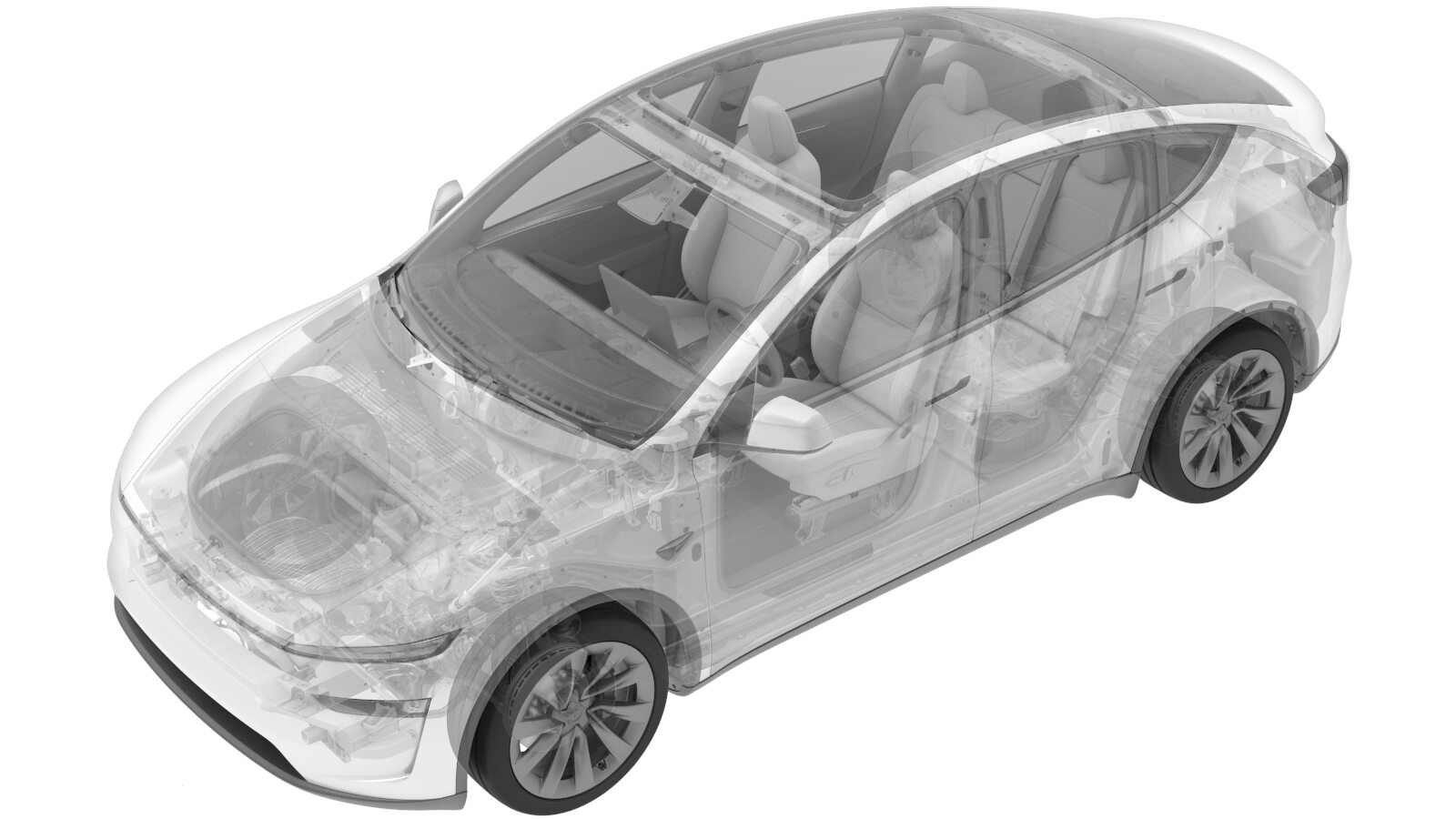
Module - Body Controller - RH (Remove and Install)
 Correction code
1715010701
FRT
0.54
NOTE: Unless
otherwise explicitly stated in the procedure, the above correction code and
FRT reflect all of the work required to perform this procedure, including
the linked procedures. Do
not stack correction codes unless explicitly told to do so.
NOTE: See Flat Rate
Times to learn more about FRTs and how
they are created. To provide feedback on FRT values, email ServiceManualFeedback@tesla.com.
NOTE: See Personal Protection
to make sure wearing proper PPE when performing the below procedure.
NOTE: See Ergonomic Precautions for safe and
healthy working practices.
Torque Specifications
| Description | Torque Value | Recommended Tools | Reuse/Replace | Notes |
|---|---|---|---|---|
| Bolt that attaches the electrical harness to the RH A-pillar |
 10 Nm (7.4 lbs-ft) |
|
Reuse | |
| Bolt that attaches the RH body control module to the body |
 6 Nm (4.4 lbs-ft) |
|
Reuse |
Remove
- Disconnect LV battery. See LV Power (Disconnect and Connect) (Modify).
- Remove the RH lower A-pillar trim. See A Pillar Lower Trim - LH (Remove and Replace).
- Remove the RH footwell hush panel. See Hush Panel - Footwell - Front Passenger (Remove and Replace).
-
Remove the bolt that attaches the electrical harness to the RH A-pillar.
TIpUse of the following tool(s) is recommended:
- SOCKET, 1/4" DR., DEEP, MAGNETIC, 10MM
-
Release the clip that attaches the connector to the RH body control module.
-
Release the connector lock, and then
disconnect the front passenger seat electrical connector from the RH body controller
module.
-
Release the lock, and then disconnect
the J7 RH front door electrical connector from the RH body controller module.
-
Disconnect the J10 instrument panel electrical connector from the RH body
controller module.
-
Disconnect the J11 HVAC electrical connector from the RH body controller
module.
-
Release the connector lock, and then
disconnect the J1 power electrical connector from the RH body controller module.
-
Disconnect the J12 body electrical
connector from the RH body controller module.
-
Release the connector lock, and then
disconnect the J4 body electrical connector from the RH body controller module.
-
Disconnect the J6 underhood storage
unit electrical connector from the RH body controller module.
-
Release the connector lock, and then
disconnect the J2 body electrical connector from the RH body controller module.
-
Disconnect the J5 body electrical
connector from the RH body controller module.
-
Release the connector locks, and then disconnect the windshield electrical connectors
(x3).
-
Remove the bolt that attaches the RH body control module to the body.
TIpUse of the following tool(s) is recommended:
- SOCKET, 1/4" DR., DEEP, MAGNETIC, 10MM
-
Release the clips (x2) that attach the electrical harness to the body at the RH
A-pillar area.
-
Remove the RH body control module from the vehicle.
- Release the clip that attaches the RH body control module to the body.
- Slide the module downward to release the tabs (x2).
- Maneuver the RH body controller module from under the IP.
Install
-
Maneuver the RH body controller module
into position under the IP carrier, and align the tabs with body cut out.
-
Install the clips (x2) that attach the electrical harness to the body at the RH
A-pillar area.
-
Install the bolt that attaches the RH body control module to the body.
 6 Nm (4.4 lbs-ft)TIpUse of the following tool(s) is recommended:
- SOCKET, 1/4" DR., DEEP, MAGNETIC, 10MM
-
Connect the windshield electrical connectors (x3).
-
Connect the J5 body electrical
connector to the RH body controller module.
-
Secure the connector lock, and then connect the J2 body electrical
connector to the RH body controller module.
-
Connect the J6 underhood storage unit
electrical connector to the RH body controller module.
-
Secure the connector lock, and then connect the J4 body electrical
connector to the RH body controller module.
-
Connect the J12 body electrical connector to the RH body controller
module.
-
Secure the connector lock, and then connect the J1 power electrical
connector to the RH body controller module.
-
Connect the J11 HVAC electrical connector to the RH body controller
module.
-
Connect the J10 instrument panel electrical connector to the RH body
controller module.
-
Secure the lock, and then connect the
J7 RH front door electrical connector to the RH body controller module.
-
Secure the connector lock, and then
connect the front passenger seat electrical connector to the RH body controller
module.
-
Install the clip that attaches the connector to the RH body control module.
-
Install the bolt that attaches the electrical harness to the RH A-pillar.
 10 Nm (7.4 lbs-ft)TIpUse of the following tool(s) is recommended:
- SOCKET, 1/4" DR., DEEP, MAGNETIC, 10MM
- Install the RH footwell hush panel. See Hush Panel - Footwell - Front Passenger (Remove and Replace).
- Install the RH lower A-pillar trim. See A Pillar Lower Trim - LH (Remove and Replace).
- Connect LV battery. See LV Power (Disconnect and Connect) (Modify).