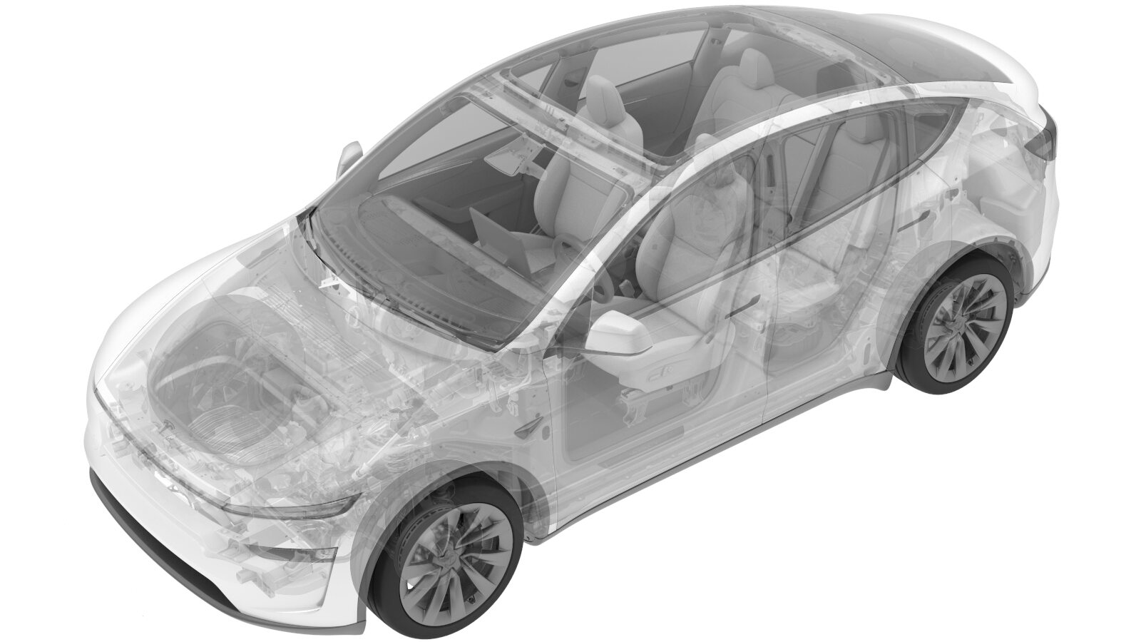
Front Energy Absorber - Ankle Catcher (Remove and Replace)
 Correction code
1001030102
FRT
0.7
NOTE: Unless
otherwise explicitly stated in the procedure, the above correction code and
FRT reflect all of the work required to perform this procedure, including
the linked procedures. Do
not stack correction codes unless explicitly told to do so.
NOTE: See Flat Rate
Times to learn more about FRTs and how
they are created. To provide feedback on FRT values, email ServiceManualFeedback@tesla.com.
NOTE: See Personal Protection
to make sure wearing proper PPE when performing the below procedure.
NOTE: See Ergonomic Precautions for safe and
healthy working practices.
Torque Specifications
| Description | Torque Value | Recommended Tools | Reuse/Replace | Notes |
|---|---|---|---|---|
| Bolts (x2) that attach the LH and RH of the cooling fan module to the ankle catcher |
 6 Nm (4.4 lbs-ft) |
|
Reuse | |
| Bolts (x2) that attach the LH and RH ankle catcher bracket to the front bumper beam |
 16 Nm (11.8 lbs-ft) |
|
||
| Bolts (x4) that attach the front end carrier to the LH and RH subframe crash cans |
 16 Nm (11.8 lbs-ft) |
|
||
| Bolts (x2) that attach the upper section of the front end carrier to the body |
 16 Nm (11.8 lbs-ft) |
|
Remove
- Remove the front fascia assembly. See Front Fascia (Remove and Install).
- Place a floor jack underneath the cooling fan module to prevent it falling.
-
Remove the bolts (x2) that attach the
LH and RH of the cooling fan module to the ankle catcher.
NoteBe careful not to lose the bolt washer.TIpUse of the following tool(s) is recommended:
- 8 mm socket
Figure 1. LH shown, RH similar -
Remove the bolts (x2) that attach the
LH and RH ankle catcher bracket to the front bumper beam.
TIpUse of the following tool(s) is recommended:
- 13 mm socket
-
Remove the bolts (x4) that attach the front end carrier to the LH and RH subframe
crash cans.
TIpUse of the following tool(s) is recommended:
- 13 mm socket
Figure 2. LH shown, RH similar -
Loosen the bolts (x2) that attach the upper section of the front end carrier to the
body.
NoteThis is to move the front end carrier to release the tabs.TIpUse of the following tool(s) is recommended:
- 13 mm socket
Figure 3. LH shown, RH similar -
Slightly pull the front end carrier away to release the tabs (x2) that attach the
ankle catcher to the front end carrier, and then rotate the rear of the ankle catcher
downward and toward the front of the vehicle to remove it.
Install
-
Slightly pull the front end carrier
away from the ankle catcher, and then position the ankle catch on the vehicle to install
the tabs (x2) that attach the ankle catcher to the front end carrier.
NoteRotate the rear of the ankle catcher up and toward the rear of the vehicle.
-
Hand-tighten the bolts (x4) that attach the front end carrier to the LH and RH
subframe crash cans.
Figure 4. LH shown, RH similar -
Torque the bolts (x4) that attach the front end carrier to the LH and RH subframe
crash cans.
 16 Nm (11.8 lbs-ft)TIpUse of the following tool(s) is recommended:
- 13 mm socket
Figure 5. LH shown, RH similar -
Install the bolts (x2) that attach the upper section of the front end carrier to the
body.
 16 Nm (11.8 lbs-ft)TIpUse of the following tool(s) is recommended:
- 13 mm socket
Figure 6. LH shown, RH similar -
Install the bolts (x2) that attach the LH and RH ankle catcher bracket to the front
bumper beam.
 16 Nm (11.8 lbs-ft)TIpUse of the following tool(s) is recommended:
- 13 mm socket
-
Hand-tighten the bolts (x2) that attach the LH and RH of the cooling fan module to
the ankle catcher.
NoteBe careful not to lose the bolt washer.TIpUse of the following tool(s) is recommended:
- 8 mm socket
Figure 7. LH shown, RH similar -
Torque the bolts (x2) that attach the
LH and RH of the cooling fan module to the ankle catcher.
 6 Nm (4.4 lbs-ft)TIpUse of the following tool(s) is recommended:
- 8 mm socket
Figure 8. LH shown, RH similar - Remove the floor jack from underneath the cooling fan module.
- Install the front fascia assembly. See Front Fascia (Remove and Replace).