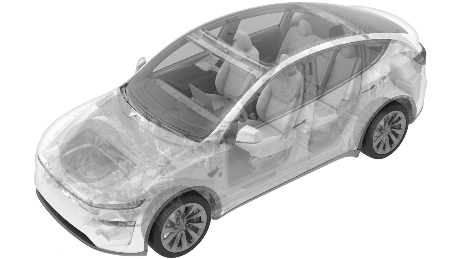
Bushing- Gearcase (Remove and Replace)
 Correction code
3901020202
FRT
0.50
NOTE: Unless
otherwise explicitly stated in the procedure, the above correction code and
FRT reflect all of the work required to perform this procedure, including
the linked procedures. Do
not stack correction codes unless explicitly told to do so.
NOTE: See Flat Rate
Times to learn more about FRTs and how
they are created. To provide feedback on FRT values, email ServiceManualFeedback@tesla.com.
NOTE: See Personal Protection
to make sure wearing proper PPE when performing the below procedure.
NOTE: See Ergonomic Precautions for safe and
healthy working practices.
- 1137785-00-A Kit, Drive Unit Bushing R&R, Model 3
- 1494178-00-A Raven Drive Unit Cradle
| Description | Torque Value | Recommended Tools | Reuse/Replace | Notes |
|---|---|---|---|---|
| Bolt that attaches the LH motor mount to the LH motor mount bracket |
 105 Nm (77.4 lbs-ft) |
|
Reuse | |
| Bolt that attaches the RH motor mount to the RH motor mount bracket |
 105 Nm (77.4 lbs-ft) |
|
Reuse | |
| Bolt that attaches front drive unit mount to the front subframe |
 80 Nm (59.0 lbs-ft) |
|
Reuse |
Remove
- Remove the front aero shield. See Aero Shield - Front (Remove and Replace).
-
Place the front drive unit stand and the underhoist stand under the front
drive unit.
NoteAlign the stand with the drive unit mounting position.NoteStop lifting once the front drive unit stand reaches the correct position.
-
Remove the bolt that attaches the LH motor mount to the LH motor mount bracket.
TIpUse of the following tool(s) is recommended:
- External Torx E18
-
Remove the bolt that attaches the RH
motor mount to the RH motor mount bracket.
TIpUse of the following tool(s) is recommended:
- External Torx E18
-
Remove the bolt that attaches front
drive unit mount to the front subframe.
TIpUse of the following tool(s) is recommended:
- 18 mm socket
-
Lower the front drive unit slightly,
and then pry the front drive unit rearward and downward to separate the front drive
unit from the subframe.
-
Install the bushing removal cups and the threaded stud onto the gearbox
bushing, and then use cups K, A, H, and L to press the bushing out of the
front drive unit gearbox.
NoteAlways apply torque to the bearing when driving the bushing.TIpUse of the following tool(s) is recommended:
- Drive Unit Bushing Kit - 1137785-00-A
- Combination Wrench 12pt 22mm
- Ratcheting Combination wrench Fixed head 22mm
-
Remove the cups and the old bushing from the threaded stud.
Install
-
Position the gearbox bushing and the
installation cups to the front drive unit gearbox, and then use cups L, H, and D to
press the bushing into the front drive unit gearbox.
NoteAlways apply torque to the bearing when driving the bushing.TIpUse of the following tool(s) is recommended:
- Drive Unit Bushing Kit - 1137785-00-A
- Combination Wrench 12pt 22mm
- Ratcheting Combination wrench Fixed head 22mm
- Remove the bushing installation cups from the front drive unit.
-
Adjust the front drive unit to the
horizontal position, and then raise the front drive unit up to the installation position
to install the front drive unit.
TIpUse of the following tool(s) is recommended:
- Transmission Jack
- Raven Drive Unit Cradle - 1494178-00-A
-
Hand-tighten the bolt that attaches front drive unit mount to the front
subframe.
-
Hand-tighten the bolt that attaches
the LH motor mount to the LH motor mount bracket.
-
Hand-tighten the bolt that attaches
the RH motor mount to the RH motor mount bracket.
-
Tighten the bolt that attaches front drive unit mount to the front subframe.
 80 Nm (59.0 lbs-ft)TIpUse of the following tool(s) is recommended:
- 18 mm socket
-
Tighten the bolt that attaches the LH motor mount to the LH motor mount bracket.
 105 Nm (77.4 lbs-ft)TIpUse of the following tool(s) is recommended:
- External Torx E18
-
Tighten the bolt that attaches the RH motor mount to the RH motor mount bracket.
 105 Nm (77.4 lbs-ft)TIpUse of the following tool(s) is recommended:
- External Torx E18
- Remove the front drive unit stand and the underhoist stand from underneath the front drive unit.
- Remove the front aero shield. See Aero Shield - Front (Remove and Replace).