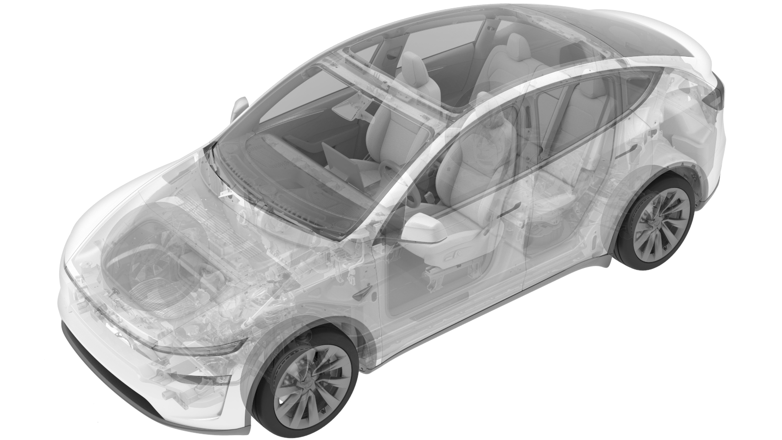
Seal - HV Input Header (Remove and Replace)
 Correction code
1630022302
FRT
0.84
NOTE: Unless
otherwise explicitly stated in the procedure, the above correction code and
FRT reflect all of the work required to perform this procedure, including
the linked procedures. Do
not stack correction codes unless explicitly told to do so.
NOTE: See Flat Rate
Times to learn more about FRTs and how
they are created. To provide feedback on FRT values, email ServiceManualFeedback@tesla.com.
NOTE: See Personal Protection
to make sure wearing proper PPE when performing the below procedure.
NOTE: See Ergonomic Precautions for safe and
healthy working practices.
Torque Specifications
| Description | Torque Value | Recommended Tools | Reuse/Replace | Notes |
|---|---|---|---|---|
| Bolt securing the busbar cover access door |
 9 Nm (6.6 lbs-ft) |
|
Reuse | |
| Bolts (x2) that attach the charge port busbar kit to the HV header |
 9 Nm (6.6 lbs-ft) |
|
Reuse | |
| Bolts (x4) that attach the input header seal to the ancillary bay |
 10 Nm (7.4 lbs-ft) |
|
Reuse |
Remove
- Disconnect LV power. See LV Power (Disconnect and Connect) (Modify).
- Remove the LH and RH 2nd row seats. See 2nd Row Seat 5 Seater - LH (Remove and Install) and 2nd Row Seat 5 Seater - RH (Remove and Install).
- Perform Vehicle HV Disablement Procedure. See Vehicle HV Disablement Procedure.
-
Remove the bolt securing the busbar
cover access door.
TIpUse of the following tool(s) is recommended:
- SKT, 1/4" SQ DR, 10MM, UNIV, HV INSULATED
-
Remove the bolts (x2) that attach the
charge port busbar kit to the HV header.
TIpUse of the following tool(s) is recommended:
- SKT, 1/4" SQ DR, 10MM, UNIV, HV INSULATED
-
Release the clip that attaches the LH body harness to the rear body, partially remove
the LH B-pillar lower trim by releasing the push clip, and then partially pull out the
harness for access.
-
Use an inflatable air bag to lift the
busbar kit connector away from the HV header.
NoteDuring the process, note the following:
- Hold the busbar firmly as there is tension on.
- Avoid damaging the harness bracket.
-
Remove the bolts (x4) that attach the
input header seal to the ancillary bay.
TIpUse of the following tool(s) is recommended:
- Penthouse Socket, 1/4" Dr, 5-Lobe, E-Torx Mag
-
Release the location pins (x2) to
remove the input header seal from the ancillary bay.
Install
-
Align the location pins (x2) and
install the input header seal to the ancillary bay.
NoteCheck the sealing ring for damage, and replace the input header seal if necessary.
-
Install the bolts (x4) that attach the
input header seal to the ancillary bay.
 10 Nm (7.4 lbs-ft)TIpUse of the following tool(s) is recommended:
- Penthouse Socket, 1/4" Dr, 5-Lobe, E-Torx Mag
NoteMark the bolts after torque. -
Use IPA wipes to clean the HV
connector contact surface and the busbar HV connector contact surface of the residual
Penetrox. Allow one minute of drying time for each surface.
NoteA new busbar comes with Penetrox pre-applied to the HV connector; clean the contact surface of the busbar HV connector when reusing a busbar.
-
Apply Penetrox onto the HV connector
joints. Apply 2 drops of Penetrox A-13 (about 5mm in diameter) on each side of the hole
on both leads, and spread evenly to ensure full coverage of the contact surface.
-
Remove the inflatable air bag from
under the HV header.
-
Position the busbar kit connector,
lower it onto the HV header while lifting the rear end of the busbar assembly to ease
installation.
NoteInspect for damage and replace if excessive force is needed to seat the busbar.
-
Install the bolts (x2) that attach the
charge port busbar kit to the HV header.
 9 Nm (6.6 lbs-ft)TIpUse of the following tool(s) is recommended:
- SKT, 1/4" SQ DR, 10MM, UNIV, HV INSULATED
NoteMark the bolts after torque. -
Perform Hioki resistance test at each
of the 2 HV joints from HV busbar lead to bolt head; acceptable resistance is 0.050 mΩ
(50 μΩ) to 0.195 mΩ (195 μΩ).
- If above 0.195 mΩ, stop work and escalate to Toolbox session;
- If below 0.050 mΩ, reposition probes and remeasure;
- If repeatedly between 0.00 mΩ and 0.050 mΩ, test passed, proceed to next step.
-
Install the bolt securing the busbar
cover access door.
 9 Nm (6.6 lbs-ft)TIpUse of the following tool(s) is recommended:
- SKT, 1/4" SQ DR, 10MM, UNIV, HV INSULATED
-
Position the LH rear body harness under the LH lower C-pillar trim, secure the clip
that attaches the harness to the rear body, and then partially by securing the push
clip.
- Install the LH and RH 2nd row seats. See 2nd Row Seat 5 Seater - LH (Remove and Install) and 2nd Row Seat 5 Seater - RH (Remove and Install).
- Connect LV power. See LV Power (Disconnect and Connect) (Modify).