HV Harness - Rear Drive Unit - RH (Tri Motor) (Remove and Replace)
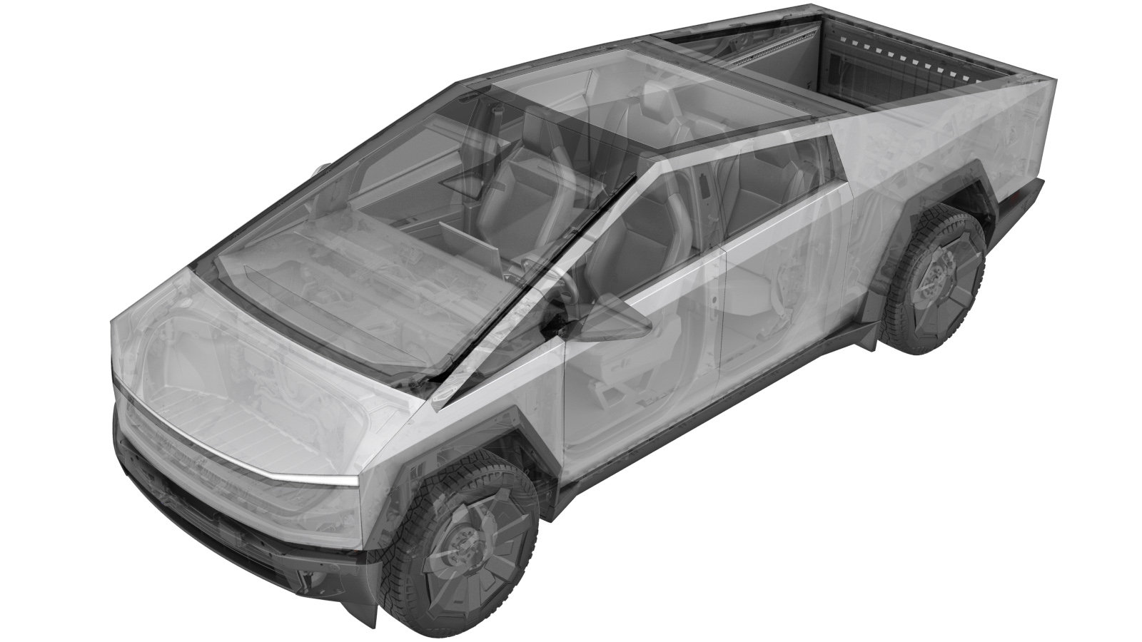 Correction code
4450074092
FRT
2.88
NOTE: Unless
otherwise explicitly stated in the procedure, the correction code and its
associated FRT reflect all of the work required to perform this procedure,
including the linked procedures. Do not stack correction
codes unless explicitly told to do so.
NOTE: See Flat Rate Times to
learn more about FRTs and how they are created.
NOTE: See Personal Protection to make
sure you are wearing proper PPE when performing the procedure below.
NOTE: See Ergonomic Precautions for safe and healthy
working practices.
Correction code
4450074092
FRT
2.88
NOTE: Unless
otherwise explicitly stated in the procedure, the correction code and its
associated FRT reflect all of the work required to perform this procedure,
including the linked procedures. Do not stack correction
codes unless explicitly told to do so.
NOTE: See Flat Rate Times to
learn more about FRTs and how they are created.
NOTE: See Personal Protection to make
sure you are wearing proper PPE when performing the procedure below.
NOTE: See Ergonomic Precautions for safe and healthy
working practices.
High Voltage Awareness Care Pointsfor additional glove and safety information.
- Open the LH front door and lower the LH front window.
- Open the powered frunk.
- Raise and support the vehicle. See Raise Vehicle - 2 Post Lift.
- Place the vehicle into Service Mode. See Service Mode.
- Unlock the vehicle Gateway. See Gateway (Unlock).
-
Access thermal system routines using the UI
NoteSelect quick controls > Service mode > Diagnostics > Thermal, Authorize routines by holding right turn signal, depressing brake pedal for 10 seconds with key on phone dock
-
Select 'Coolant System' to enter coolant circuit screen, Select 'Coolant Fill/Drain' using the UI and PROC_VCFRONT_X_START-THERMAL-FILL-DRAINvia Service Mode:
- Thermal ➜ Actions ➜ Start Thermal Fill/Drain
- Thermal ➜ Coolant System ➜ Start Coolant Fill/Drain
- Thermal ➜ Refrigerant System ➜ Start Refrigerant Fill/Drain
- Drive Unit ➜ Front Drive Unit Replacement ➜ Start Coolant Fill/Drain
- Drive Unit ➜ Rear Drive Unit Replacement ➜ Start Coolant Fill/Drain
NoteVerify indicator displays green for Coolant readiness, Thermal Fill Drain routine has a 50 minute time limit - Connect a laptop with Toolbox to the vehicle. See Toolbox 3 (Connect and Disconnect).
- Select "Actions" and search for "EPB"
-
Select PROC_EPB_X_SERVICE-MODEvia Service Mode:
- Chassis ➜ Brakes ➜ EPB Service Mode
- Chassis ➜ Brakes ➜ EPB Service Mode
NoteChoose 'BOTH' under "EPB Selection", Choose 'START' under "Action Selection", Chock wheel if necessary, Select ‘X’ at top right of window to close once complete - Remove the rear underhood apron. See Underhood Apron - Rear (Remove and Install).
- Disconnect MV power. See Mid-Voltage Power (Disconnect and Connect) (Modify).
- Remove the LH and RH rear wheels. See Wheel Assembly (Remove and Install).
-
Disconnect RH rear EPB harness
Note1x connector, Release locking tab
-
Release RH rear brake line from upper control arm
Note1x bolt, 10mm, 10 Nm
-
Remove RH rear brake caliper and set aside
Note2x bolts, 21 mm, 150 Nm, Hang caliper from body if not fully removing, Route caliper hose so that it does not get caught on stabar assembly
-
Remove RH rear brake rotor
NoteRotor will be loose until caliper is installed
-
Use jack to simulate ride height on RH rear suspension
NoteRaise jack to simulate ride height, This is to release tension from the upper control arm which will be removed next later steps, DO NOT skip this you run into the risk of hurting yourself
-
Remove RH rear toe link from RH rear knuckle
Note1x nut, 21mm, 170 Nm, Counter hold ball joint, Discard nyloc nut after removal
-
Remove nut securing RH rear upper control arm to knuckle
Note1x nylon nut, 21 mm, 150 Nm, Discard nut after removal, Place support stand below suspension to ease removal
-
Use jack to lower RH rear ride height back to hanging position
NoteLower jack to let suspension hang
-
Release harness from RH rear air spring module
Note2x connectors, 1x grommet
-
Remove RH rear lower control arm aeroshield
Note3x bolts, 10mm, 7 Nm
-
Remove nuts securing RH rear air spring module to lower control arm
Note2x nylon nut, 21 mm, 140 Nm, Discard nuts after removal
-
Disconnect EPB harness connector from LH rear brake caliper
Note1x connector, Release locking tab
-
Release LH rear brake line from upper control arm
Note1x bolt, 10mm, 10 Nm
-
Remove LH rear brake caliper and set aside
Note2x bolts, 21 mm, 150 Nm, Hang caliper from body if not fully removing, Route caliper hose so that it does not get caught on stabar assembly
-
Remove LH rear brake rotor
NoteRotor will be loose until caliper is installed
-
Use jack to simulate ride height on LH rear suspension
NoteRaise jack to simulate ride height, This is to release tension from the upper control arm which will be removed next later steps, DO NOT skip this you run into the risk of hurting yourself
-
Remove LH rear toe link from LH rear knuckle
Note1x nut, 21mm, 170 Nm, Counter hold ball joint, Discard nyloc nut after removal
-
Remove nut securing LH rear upper control arm to knuckle
Note1x nylon nut, 21 mm, 150 Nm, Discard nut after removal, Move brake hose aside to avoid damage, Use caution when releasing rear upper control from knuckle
-
Use jack to lower LH rear ride height back to hanging position
NoteLower jack to let suspension hang
-
Release harness from LH rear air spring module
Note2x connectors, 1x grommet
-
Remove LH rear lower control arm aeroshield
Note3x bolts, 10mm, 7 Nm
-
Remove nuts securing LH rear air spring module to lower control arm
Note2x nylon nut, 21 mm, 140 Nm, Discard nuts after removal
- Remove rear skid plate. See Skid Plate - Rear (Remove and Install).
- Remove the rear aeroshield. See Aeroshield - Rear (Remove and Install).
- Remove the rear diffuser. See Diffuser - Rear (Remove and Install).
-
Remove all items from pockets and ensure not wearing metal items
-
Inspect HV insulating gloves
NoteCheck gloves for damage prior to use, Refer to service document TN-15-92-003, for information on inspecting HV gloves.
-
Put on HV insulating gloves and leather over gloves
-
Remove clips securing AC compressor HV harness
Note3x clips
-
Verify no HV - Install amp clamp to RDU HV harness
NoteVerify meter is zeroed out before performing measurement, Measure single cable. Verify ammeter is installed in correct direction. If current > 0.5A do not proceed with disconnecting HV connector. In this case, start vehicle electrical isolation again to make sure that all was properly shut down. Escalate for assistance as required. If current < 0.5A, Ok to disconnect and check voltage at HV plug on the battery side. Release locking tab and rotate the release lever up to disengage the connector, Release harness clip, Do not force the release lever up, Ensure the alignment tabs on the RDU header are not damaged. Make sure to wear PPE (HV gloves, safety glasses) when working on high voltage component, Measure B+ to Ground, B- to Ground, B+ to B-, If voltage is greater than 10V, Pack contactors are not open or welded, Stop work and reach out to Service Engineering
-
Disconnect RDU HV harness
Note1x connector, Release locking tab and rotate release lever up, Do not force release lever up, Ensure alignment tabs on header are not damaged
- Remove leather over gloves and HV insulating gloves
-
Position coolant drain container underneath RH rear of HV battery
-
Remove front lower clips securing RH rear wheel arch liner
Note3x clips
-
Disconnect RDU return hose from PT return hose
Note1x spring clip, 1x clamp clip, Move wheel liner aside as needed, Plug coolant connections as needed
-
Disconnect RDU supply hose from HV battery
Note1x spring clip, Plug coolant connections as needed
- Remove coolant drain container from underneath vehicle
-
Disconnect rear steering gear harness from subframe
Note1x connector, Release red locking tab
-
Disconnect rear subframe harness from rear fascia harness
Note3x connectors
-
Release rear diffuser brackets and set aside
Note6x bolts, 13mm, 30 Nm, 4x tabs, Let brackets hang
-
Lower vehicle partially and set lift onto locks
NoteRaise lift off locks, then hold lock release lever to keep locks free while vehicle is lowered, Set vehicle to comfortable working height
-
Position powertrain lift under rear subframe
-
Connect shop air supply to powertrain table
-
Raise powertrain lift to rear subframe
NoteMake sure the height setting of the hoist can be reached with the powertrain lift height limit
-
Safely secure rear subframe onto powertrain lift
NoteSecure subframe to powertrain table and fixture
-
Remove bolts securing rear subframe to body
Note4x bolts, 24mm, 355 Nm
-
Lower subframe table to access breather tube
NoteUse caution with RDU coolant hoses and breather line, Subframe jig assembly will need to be maneuvered to prevent coolant lines getting caught, Access breather from LH rear wheel well
-
Disconnect RDU breather tube
Note2x tabs, 1x clip, Press tabs inward and pull breather up, Release clip from RDU casing
-
Fully lower subframe table
NoteUse caution with RDU coolant hoses, Subframe table will need to be moved back to prevent coolant lines getting caught, Ensure DU breather line is not caught
-
Disconnect air supply from subframe lifting tool
-
Remove RH RDU inverter to chiller hose
Note2x spring clips, Plug coolant connections as needed
-
Remove clip securing RSA jumper harness to RHS RDU HV harness
Note1x clip
-
Disconnect RHS RDU harness
Note1x connector, Release locking tab and rotate release lever up, Do not force release lever up, Ensure alignment tabs on header are not damaged
-
Remove RHS RDU harness
Note5x bolts, 10mm, 12 Nm
-
Install RHS RDU harness
Note5x bolts, 10mm, 12 Nm
-
Connect RHS RDU harness
Note1x connector, Verify lever is upright and in open position, Carefully seat connector and allow lever to engage, Fully secure lever and verify red tab is locked, Do not damage any pins
-
Install clip securing RSA jumper harness to RHS RDU HV harness
Note1x clip
-
Install RH RDU inverter to chiller hose
Note2x spring clips, Remove plugs as needed
-
Position subframe lifting tool with subframe assembly under vehicle
-
Connect air supply to subframe lifting tool
-
Raise drive unit until sufficient access is available to breather
NoteRecommend assistance, Use caution to not damage components while raising subframe, Position coolant lines above HV battery lip
-
Connect RDU breather tube
Note2x tabs, 1x clip, Install clip onto RDU casing, Verify tabs are fully engaged
-
Fully raise rear drive unit and subframe into position
NoteRecommend assistance, Use caution to not damage components while raising subframe, Position coolant lines above HV battery lip
-
Loosely install bolts securing rear subframe to body
Note4x bolts, 24mm, Hand Tight, Start bolts by hand before using power tools
-
Torque rear subframe bolts
Note4x bolts, 24mm, 355 Nm
-
Remove rear subframe tie downs from powertrain lift
NoteRelease subframe to powertrain table and fixture
-
Lower powertrain table from subframe and move away from vehicle
-
Secure rear diffuser brackets
Note6x bolts, 13mm, 30 Nm, 4 tabs
-
Connect tri motor rear subframe harness onto rear fascia harness
Note3x connectors
-
Connect rear steering gear harness
Note1x connector, Engage red locking tab
-
Position coolant drain container underneath RH rear of HV battery
-
Connect RDU supply hose onto HV battery
Note1x spring clip, Remove plugs as needed
-
Connect RDU return hose to PT return hose
Note1x spring clip, 1x clamp clip, Move wheel liner aside as needed, Remove plugs
-
Install front lower clips securing RH rear wheel arch liner
Note3x clips
- Remove coolant drain container from underneath vehicle
-
Connect RDU HV harness
Note1x connector, Verify lever is upright and in open position, Carefully seat connector and allow lever to engage, Fully secure lever and verify red tab is locked, Do not damage any pins
-
Connect LHS RDU HV harness
Note1x connector, Verify lever is upright and in open position, Carefully seat connector and allow lever to engage, Fully secure lever and verify red tab is locked, Do not damage any pins
-
Install clips securing AC compressor HV harness
Note3x clips
- Install the rear diffuser. See Diffuser - Rear (Remove and Install).
- Install the rear aeroshield. See Aeroshield - Rear (Remove and Install).
- Install rear skid plate. See Skid Plate - Rear (Remove and Install).
-
Lower vehicle partially and set lift onto locks
NoteRaise lift off locks, then hold lock release lever to keep locks free while vehicle is lowered, Set vehicle to comfortable working height
-
Install nuts securing LH rear air spring module to lower control arm assembly
Note2x nylon nut, 21 mm, 140 Nm, Install new nylon nuts
-
Install LH rear lower control arm aeroshield
Note3x bolts, 10mm, 7 Nm
-
Secure harness to LH rear active dampener
Note2x connectors, 2x grommets
-
Install nut securing LH rear upper control arm to knuckle
Note1x nylon nut, 21 mm, 150 Nm, Install new nylon nut, Counter-hold joint to install nut, Support suspension to ease installation, Ensure brake hose is properly routed
-
Install LH rear toe link onto LH rear knuckle
Note1x nut, 21mm, 170 Nm, Install new Nyloc nut
-
Install LH rear brake caliper onto LH rear knuckle
Note2x bolts, 21mm, 150 Nm
-
Connect EPB harness connector to LH rear brake caliper
Note1x connector, Engage locking tab
-
Install LH rear brake line onto upper control arm
Note1x bolt, 10 mm, 10 Nm
-
Install nuts securing RH rear air spring module to lower control arm assembly
Note2x nylon nut, 21 mm, 140 Nm, Install new nylon nuts
-
Install RH rear lower control arm aeroshield
Note3x bolts, 10mm, 7 Nm
-
Secure harness to RH rear active dampener
Note2x connectors, 2x grommets
-
Install nut securing RH rear upper control arm to knuckle
Note1x nylon nut, 21 mm, 150 Nm, Install new nylon nut, Counter-hold joint to install nut, Support suspension to ease installation
-
Install RH rear toe link onto RH rear knuckle
Note1x nut, 21mm, 170 Nm, Install new Nyloc nut
-
Install RH rear brake caliper onto RH rear knuckle
Note2x bolts, 21mm, 150 Nm
-
Connect RH rear EPB harness
Note1x connector, Engage locking tab
-
Install RH rear brake line onto upper control arm
Note1x bolt, 10 mm, 10 Nm
- Install the LH and RH rear wheels. See Wheel Assembly (Remove and Install).
- Perform cooling system vacuum refill. See Cooling System (Vacuum Refill).
- Install the rear underhood apron. See Underhood Apron - Rear (Remove and Install).
- Remove the vehicle from the lift. See Raise Vehicle - 2 Post Lift.
- Raise the LH front window and close the LH front door.