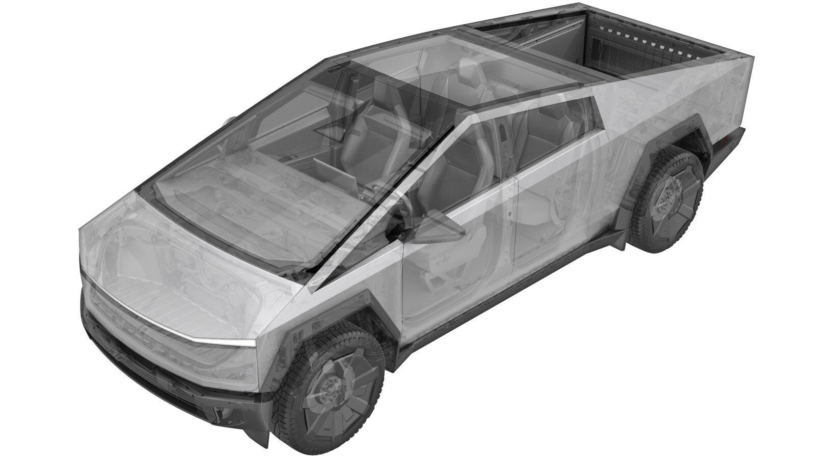
Sensor - Ride Height - Front - LH (Remove and Install)
 Correction code
3110069011
3110069012
3110069021
3110069022
FRT
0.42
NOTE: Unless
otherwise explicitly stated in the procedure, the above correction code and
FRT reflect all of the work required to perform this procedure, including
the linked procedures. Do
not stack correction codes unless explicitly told to do so.
NOTE: See Flat Rate Times to learn more about FRTs and how
they are created. To provide feedback on FRT values, email ServiceManualFeedback@tesla.com.
NOTE: See Personal Protection
to make sure wearing proper PPE when performing the below procedure.
NOTE: See Ergonomic Precautions for safe and
healthy working practices.
- 2024-09-26: Updated steps for calibration vehicle ride height to linked procedure. Ride height calibration procedure updated with expandable alignment specifications and ride height setting.
Remove
- Open the LH front door and lower the LH front window.
- Raise and support the vehicle. See Raise Vehicle - 2 Post Lift.
- Remove the LH front wheel. See Wheel Assembly (Remove and Install).
- Remove the LH front wheel liner. See Wheel Liner - Front - LH (Remove and Replace).
-
Disconnect the LH front air suspension
height sensor connector.
-
Remove and discard the nut that
attaches the LH front air suspension height sensor to the body, and then release the
sensor from the upper control arm mount.
 50 Nm (36.9 lbs-ft)TIpUse of the following tool(s) is recommended:
- 15 mm socket
-
Remove the LH front air suspension
height sensor linkage from the ball stud on the upper control arm assembly, and then
remove the sensor from the vehicle.
Install
-
Position the LH front air suspension
height sensor into the vehicle, and then install the sensor linkage onto the ball stud
on the upper control arm assembly.
-
Position the LH front air suspension
height sensor to the body, and then install a new nut that attaches the sensor to the
upper control arm mount.
 50 Nm (36.9 lbs-ft)TIpUse of the following tool(s) is recommended:
- 15 mm socket
-
Connect the LH front air suspension height sensor connector.
- Install the LH front wheel liner. See Wheel Liner - Front - LH (Remove and Replace).
- Install the LH front wheel. See Wheel Assembly (Remove and Install).
- Remove the vehicle from the lift. See Raise Vehicle - 2 Post Lift.
- Calibrate the vehicle ride height. See Ride Height Calibration.
- Exit Service Mode. See Service Mode.
- Raise the LH front window and close the LH front door.