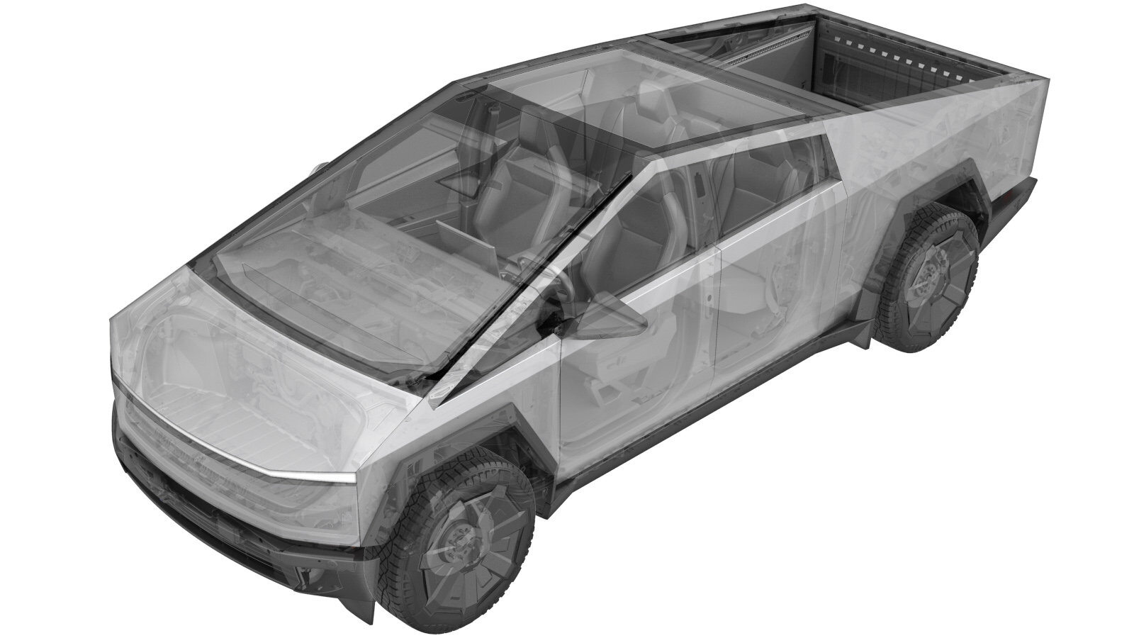
Control Module - Steering Column (Remove and Install)
 Correction code
3205111061
FRT
0.30
NOTE: Unless
otherwise explicitly stated in the procedure, the above correction code and
FRT reflect all of the work required to perform this procedure, including
the linked procedures. Do
not stack correction codes unless explicitly told to do so.
NOTE: See Flat Rate Times to learn more about FRTs and how
they are created. To provide feedback on FRT values, email ServiceManualFeedback@tesla.com.
NOTE: See Personal Protection
to make sure wearing proper PPE when performing the below procedure.
NOTE: See Ergonomic Precautions for safe and
healthy working practices.
- 2024-09-03: Removed front rack calibration UI steps.
- 2024-06-11: Added steps to perform front steering rack calibration.
- 2024-04-18: Added link to perform Handwheel calibration that includes video.
Remove
- Remove the steering column lower shroud. See Shroud - Lower - Steering Column (Remove and Install).
-
Remove and discard the clip on the SCCM electrical connector, and then disconnect the electrical connector.
CAUTIONThe steering column must remain in the centered position.NoteThe clip will break during removal.NoteThe originally installed clip is black. The replacement clip is orange.
-
Remove the bolt that attaches the SCCM to the steering column, and then carefully slide the SCCM off the steering column to remove it.
 9 Nm (6.6 lbs-ft)NoteDo not rotate the SCCM while sliding it off the steering column.TIpUse of the following tool(s) is recommended:
- 5 mm hex
Install
-
Carefully slide the SCCM onto the steering column, and then install the bolt that attaches the SCCM to the assembly.
 9 Nm (6.6 lbs-ft)TIpUse of the following tool(s) is recommended:
- 5 mm hex
CAUTIONDo not rotate the SCCM while sliding it onto the steering column.CAUTIONThe steering column must remain in the centered position. -
Install a new orange clip (PN: 1028053-00-A) onto the SCCM connector, and then connect the connector.
NotePerform a push-pull-push test of the electrical connector to make sure the connector is seated properly.
-
Remove the red locking tab from the new SCCM.
CAUTIONDo not allow the clock spring to rotate.
- Install the steering column lower shroud. See Shroud - Lower - Steering Column (Remove and Install).
- Connect a laptop with Toolbox 3 to the vehicle. See Toolbox 3 (Connect and Disconnect).
- Perform Handwheel calibration. See Set Handwheel Zero.
- Disconnect Toolbox and remove the laptop from the vehicle. See Toolbox 3 (Connect and Disconnect).
- Exit Service Mode. See Service Mode.
- Raise the LH front window and close the LH front door.