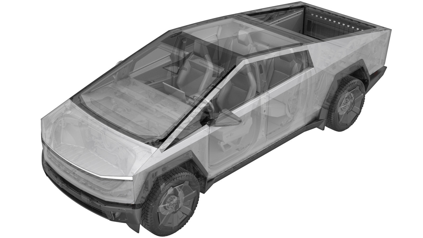
Fixed Glass Roof Assembly (Remove and Replace)
 Correction code
1020106012
1020106011
FRT
2.28
NOTE: Unless
otherwise explicitly stated in the procedure, the correction code and its
associated FRT reflect all of the work required to perform this procedure,
including the linked procedures. Do not stack correction
codes unless explicitly told to do so.
NOTE: See Flat Rate Times to
learn more about FRTs and how they are created.
NOTE: See Personal Protection to make
sure you are wearing proper PPE when performing the procedure below.
NOTE: See Ergonomic Precautions for safe and healthy
working practices.
Correction code
1020106012
1020106011
FRT
2.28
NOTE: Unless
otherwise explicitly stated in the procedure, the correction code and its
associated FRT reflect all of the work required to perform this procedure,
including the linked procedures. Do not stack correction
codes unless explicitly told to do so.
NOTE: See Flat Rate Times to
learn more about FRTs and how they are created.
NOTE: See Personal Protection to make
sure you are wearing proper PPE when performing the procedure below.
NOTE: See Ergonomic Precautions for safe and healthy
working practices.
-
- 2025-12-04: Added note for RH antenna harness routing.
- Added steps for roof glass rear edge seal.
- 2024-12-11: Added new caution about Pre-Installation Glass Inspection service requirements.
- 2024-03-12: Cleaned up topic.
Remove
- Open all the doors and lower all the windows.
- Open the powered frunk.
- Open the tailgate.
- Open the tonneau cover.
- Remove the rear underhood apron. See Underhood Apron - Rear (Remove and Install).
- Disconnect MV power. See Mid-Voltage Power (Disconnect and Connect) (Modify).
- Remove the front header trim. See Trim - Header - Front (Remove and Install).
- Remove the rear header trim. See Trim - Header - Rear (Remove and Install).
- Remove the LH and RH mid A-pillar trims. See Trim - A-Pillar - Mid - LH (Remove and Install).
- Remove the LH and RH upper A-pillar trims. See Trim - A-Pillar - Upper - LH (Remove and Install).
- Remove the LH and RH cantrail trims. See Trim - Cantrail - LH (Remove and Install).
- Remove the LH and RH roof appliques. See Applique - Roof - LH (Remove and Install).
- Remove the tonneau applique. See Tonneau Applique (Remove and Install).
-
Remove the Telematics Control Unit (TCU) as an assembly. See Telematics Control Unit (TCU) (Remove and Install).
NoteIt is not necessary to remove the TCU from the bracket.
-
Disconnect the LH and RH roof antenna electrical connectors.
Figure 1. LH roof antenna electrical connector Figure 2. RH roof antenna electrical connector -
Remove the mounting bosses from the roof assembly.
Notex3 plastic bossesNoteCut the adhesive using the equalizer with short blade.CAUTIONUse caution with the equalizer to avoid cracking the glass.
-
Cut the roof assembly interior double urethane path.
NoteCut the urethane at the front LH and RH corners using the equalizer with short blade. This will allow easier cutting of exterior path.CAUTIONUse caution with the equalizer to avoid cracking the glass.
-
Cut the roof assembly exterior rear double urethane path and datums.
Notex2 datumsNoteCut the urethane along the rear section of the roof assembly using the equalizer with long blade.NoteEnsure datums are cut at both LH and RH rear corners. This will allow easier cutting of the exterior path.CAUTIONUse caution with the equalizer to avoid cracking the glass.
-
Measure and record the gap and flush on the windshield and roof glass.
NoteMeasure at the front of windshield. Measure from the LH and RH edge to cantrail panels at the front and rear of roof assembly.NoteMeasurements will be used during the installation of the new glass.
-
Prepare the WRD Spider 3 glass removal kit.
-
Push the cutting line through to the exterior.
NoteSecure the line to tip of starting tool. Push through at an easily accessible location on the exterior.NoteKeep the tool flush to the glass to avoid contacting the body.
-
Route the cutting line around the exterior perimeter of the roof assembly.
NoteEnsure enough length is pulled through the glass.NoteVerify the line sits underneath the glass and the seal.
-
Insert the end of the nylon cord through the eye of starter tool and pull it into the inside of the body.
NoteStarting tool shall be close to the glass corner as far as possible so as to obtain relatively large space for the nylon rope to pass through.
-
Attach the anchor point to the interior of the roof assembly and secure the line.
NoteTie off the end of cutting line, and then thread the handle down.
-
Secure the interior side of the line to the spider cutting tool.
NoteFollow the instructions on the spider tool.NoteFeed the line through the opening of the cutting tool and tie a knot to secure it in place.CAUTIONIf the spindle is not turned the proper direction, the cutting tool will be damaged.
-
Secure the spider cutting tool to the interior side of the fixed roof glass assembly.
NoteNote the orientation of the cutting line.NoteEnsure the line wraps over the large pulley and holds at a 90 degree angle or greater.
-
Secure the angle driver to the powered drill.
-
Cut the remaining urethane securing the roof assembly to the body.
NoteMove the cutting tool as needed in order to keep the line close to a 90 degree angle.NoteUse plastic guard as required to guide the cutting line.
-
Remove the spider cutting tool and anchor point.
NoteRelease the suction cups.
-
Secure the suction cups (x4) to the roof glass.
-
Remove the fixed roof glass from the body.
NoteRecommend assistance.
-
Remove the suction cups (x4) from the old roof glass.
-
Remove the old urethane from the body, and then wipe the body with Isopropyl Alcohol (IPA) wipes to clean the surface.
NoteAllow 1 minute dry time.
-
Remove the foam from body at roof
glass rear edge.
NoteVehicles built after August 11, 2025 will not have foam. If the vehicle was built after August 11, 2025, then skip this step.
-
Remove the adhesive residue from the
body at the roof glass rear edge.
NoteVehicles built after August 11, 2025 will not have foam. If the vehicle was built after August 11, 2025, then skip this step.
-
Wipe body with IPA to clean
surface.
NoteAllow to 1 minute dry time.
Install
-
Without removeing the red adhesive
backing, position the seal onto the roof glass rear edge, and then use masking tape to
hold the seal in place.
NoteAlign seal with glass edge and net pads.NoteIf the new glass comes with the seal already installed, then skip this step.
-
Starting from one end of the seal,
remove the red adhesive backing to adhere the seal onto roof glass rear edge.
NotePull the red backing, and then press seal onto glass. Remove the masking tape as needed.NoteMake sure the rear edge seal does not overlap with the LH and RH edge seals.NoteIf the new glass comes with the seal then skip this step.
-
Attach the suction cups (x4) to the new roof assembly.
NotePlace the suction cups to allow easy lifting of the glass.
-
Apply primer to the vehicle body on the urethane path.
NoteApply primer to any exposed metal.NoteAllow primer to dry for two minutes before installing the roof assembly.NoteWipe away any primer drips with IPA wipes.
-
Prepare the caulking gun and urethane.
NoteOpening must be 12 mm wide and 18 mm tall.
-
Apply urethane to the roof assembly.
Note3 tubes of urethane are required.NoteFollow the primer path.NoteEnsure overlap occurs at the rear center of glass.
-
Install the roof assembly onto the vehicle.
NoteRecommend assistance.NoteAlign the datums at the rear of the roof assembly.
-
Push the glass downwards.
NoteFirmly push downwards around the perimeter of the glass.NoteHeight datums will not allow the glass to become under-flush.
- Install the tonneau applique. See Tonneau Applique (Remove and Install).
-
Verify and adjust the gap and flush between the windshield and the roof glass.
NoteMeasure at the windshield and between the roof edge to cantrail panel, and adjust if necessary.NoteRefer to measurements taken during removal.Note
- Install the LH and RH roof appliques. See Applique - Roof - LH (Remove and Install).
-
Apply tape to secure the roof glass.
NoteTape to the windshield to ensure the roof glass will not shift.
-
Remove the suction cups (x4) from the roof.
-
Reposition the windshield seal, if necessary.
NoteSpray glass cleaner to lubricate the seal, if necessary.
-
Connect the LH and RH roof antenna electrical connectors.
NoteIf the RH antenna harness is too short, route the antenna harness inbetween the main harness and body.
Figure 3. LH roof antenna electrical connector Figure 4. RH roof antenna electrical connector - Install the Telematics Control Unit (TCU). See Telematics Control Unit (TCU) (Remove and Install).
- Install the LH and RH cantrail trims. See Trim - Cantrail - LH (Remove and Install).
- Install the LH and RH upper A-pillar trims. See Trim - A-Pillar - Upper - LH (Remove and Install).
- Install the LH and RH mid A-pillar trims. See Trim - A-Pillar - Mid - LH (Remove and Install).
- Install the rear header trim. See Trim - Header - Rear (Remove and Install).
- Install the front header trim. See Trim - Header - Front (Remove and Install).
- Reconnect MV power. See Mid-Voltage Power (Disconnect and Connect) (Modify).
- Install the rear underhood apron. See Underhood Apron - Rear (Remove and Install).
- Close the powered frunk.
- Close the tonneau cover.
- Close the tailgate.
- Raise all the windows and close all the doors.