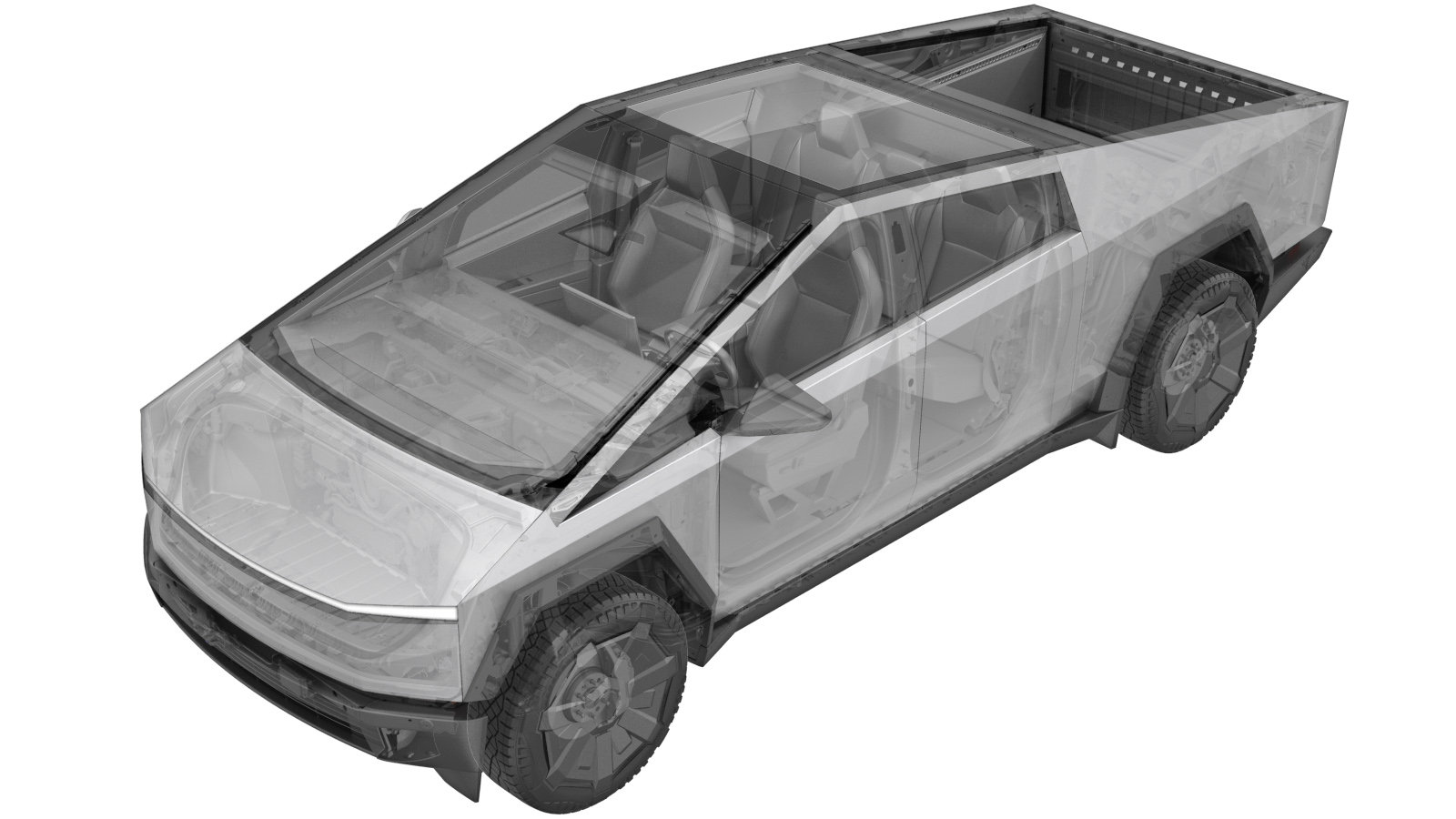
Center Display Cable Overlay (Repair)
 Correction code
1710029008
0.84
NOTE: Unless
otherwise explicitly stated in the procedure, the above correction code and
FRT reflect all of the work required to perform this procedure, including
the linked procedures. Do
not stack correction codes unless explicitly told to do so.
NOTE: See Flat Rate Times to learn more about FRTs and how
they are created. To provide feedback on FRT values, email ServiceManualFeedback@tesla.com.
NOTE: See Personal Protection
to make sure wearing proper PPE when performing the below procedure.
NOTE: See Ergonomic Precautions for safe and
healthy working practices.
- Remove lower IP panel. See Lower Assembly - Instrument Panel (Remove and Install).
- Remove the glovebox assembly. See Glovebox Assembly (Remove and Install).
- Remove the center display assembly. See Touchscreen - Center Display Assembly (Remove and Install).
-
Disconnect center display cable from car computer
-
Cut display side of display cable and wrap with tape
NoteRefer to cable overlay guidelines: TN-20-17-001
-
Cut car computer side of display cable and wrap with tape
NoteRefer to cable overlay guidelines: TN-20-17-001
-
Position center display cable onto IP carrier
NoteRefer to cable overlay guidelines: TN-20-17-001
-
Secure center display cable onto IP carrier
NoteRefer to cable overlay guidelines: TN-20-17-001, cable ties x 15
-
Connect enter display cable to car computer
- Install the center display assembly. See Touchscreen - Center Display Assembly (Remove and Install).
- Install the glovebox assembly. See Glovebox Assembly (Remove and Install).
- Install lower IP panel. See Lower Assembly - Instrument Panel (Remove and Install).