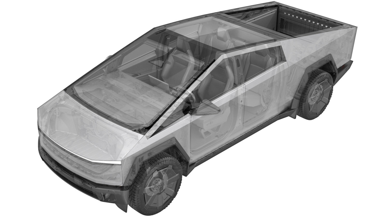
Fill Port - Air Suspension (Remove and Install)
 Correction code
N/A
FRT
0.30
NOTE: Unless
otherwise explicitly stated in the procedure, the above correction code and
FRT reflect all of the work required to perform this procedure, including
the linked procedures. Do
not stack correction codes unless explicitly told to do so.
NOTE: See Flat Rate Times to learn more about FRTs and how
they are created. To provide feedback on FRT values, email ServiceManualFeedback@tesla.com.
NOTE: See Personal Protection
to make sure wearing proper PPE when performing the below procedure.
NOTE: See Ergonomic Precautions for safe and
healthy working practices.
- 2024-05-13: Corrected psi value to 261 psi (18 bar).
Remove
- Open the LH front door and lower the LH front window.
- Raise and support the vehicle on a 2 post lift. See Raise Vehicle - 2 Post Lift.
- Put the vehicle in Service Mode. See Service Mode.
- Unlock the vehicle gateway. See Gateway (Unlock).
-
Deflate the TAS system through the
vehicle touchscreen.
NoteTouch Service > Chassis > Suspension > Service > Deflate All, and then touch Run. Close it once the routine passed.
- Remove the RH rear fender flare. See Fender Flare - Rear - RH (Remove and Install).
- Remove the RH rear fender flare carrier. See Carrier - Fender Flare - Aft - Rear - RH (Remove and Install).
-
Release the clips (x2) that attach the
air suspension fill tube to the body.
Notex1 datumNoteRelease the datum, and then slide the clip away from the body.
-
Remove the air suspension fill port
assembly.
TIpUse of the following tool(s) is recommended:
- 12 mm flare nut
NoteHand tight.NoteCounter-hold the nut while turning the plastic body.
Install
-
Verify the aluminum valve is properly
installed onto the plastic fill port.
 3.5 Nm (2.6 lbs-ft)TIpUse of the following tool(s) is recommended:
- 17 mm
NoteMake sure the valve is flush with the plastic body. Any gap will cause the O-ring to pop out. -
Install the air suspension fill port
assembly.
TIpUse of the following tool(s) is recommended:
- 12 mm flare nut
NoteHand tight.NoteCounter-hold the nut while turning the plastic body. -
Fasten the clips (x2) that attach the
air suspension fill tube to the body.
Notex1 datum
-
Set up nitrogen tank kit
(1083876-00-A) to fill the air reservoir.
NoteVerify valves are set to closed position on the tank, the regulator, and the air line.
-
Connect the nitrogen tank hose onto
the air reservoir fill port.
-
Open the valve on the nitrogen tank,
and then set pressure using the regulator.
NoteSlowly open valve and adjust the regulator. Verify the pressure is set to 18 bar (261 psi).
-
Open the valve on the nitrogen tank
hose.
-
Verify that pressure holds on the
regulator valve gauge.
Note18 bar (261 psi)NoteIf the pressure does not hold, there may be a leak present.
-
Close the valve on the nitrogen tank
hose.
-
Close the valve on the nitrogen
tank.
-
Close the pressure regulator valve on
the nitrogen tank to release pressure in lines.
-
Disconnect the nitrogen tank hose from
the air reservoir fill port.
- Install the RH rear fender flare carrier. See Carrier - Fender Flare - Aft - Rear - RH (Remove and Install).
- Install the RH rear fender flare. See Fender Flare - Rear - RH (Remove and Install).
-
Put the vehicle in TAS normal mode
using the vehicle touchscreen.
NoteTouch Service > Chassis > Suspension > Normal.
-
Verify the operation of the air
suspension.
NoteCycle the ride height through the vehicle touchscreen: Controls > Suspension > Low to Very High.NoteAll doors must be closed to allow ride height to cycle.NoteSet the air suspension back to ''Standard'' after verification.
- Remove the vehicle from the lift. See Raise Vehicle - 2 Post Lift.
- Exit Service Mode. See Service Mode.
- Raise the LH front window and close the LH front door.