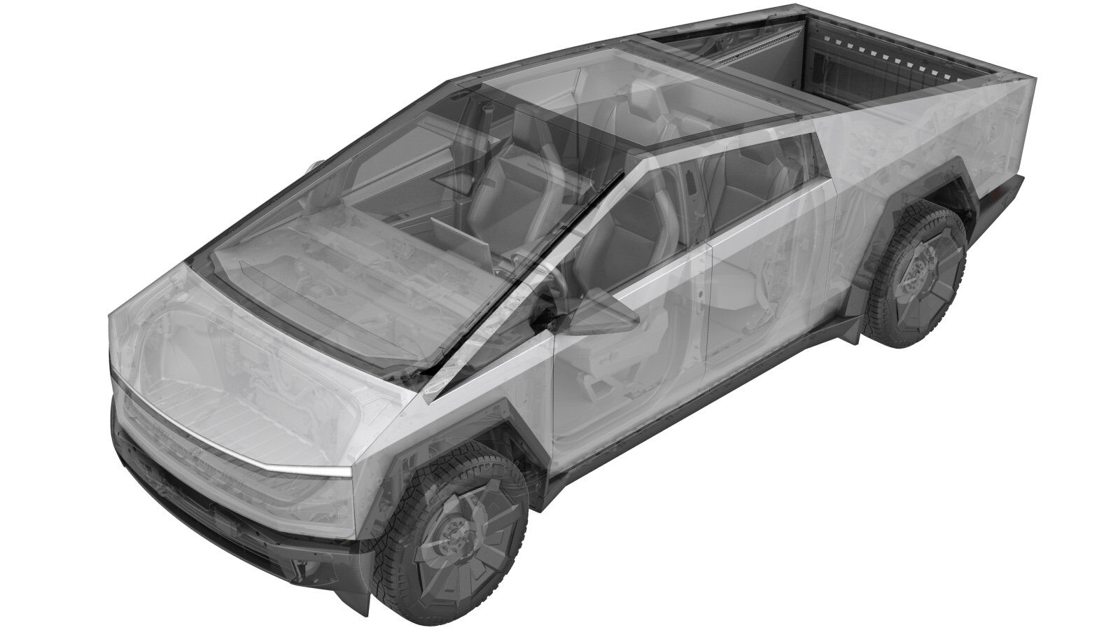
Disconnect MV Power (Modify)
 Correction code
17010200
FRT
0.05
NOTE: Unless
otherwise explicitly stated in the procedure, the above correction code and
FRT reflect all of the work required to perform this procedure, including
the linked procedures. Do
not stack correction codes unless explicitly told to do so.
NOTE: See Flat Rate Times to learn more about FRTs and how
they are created. To provide feedback on FRT values, email ServiceManualFeedback@tesla.com.
NOTE: See Personal Protection
to make sure wearing proper PPE when performing the below procedure.
NOTE: See Ergonomic Precautions for safe and
healthy working practices.
- 2024-10-16: Updated MV battery connector lever images.
- 2024-09-13: Updated MV battery reconnection process.
- 2024-09-06: Updated MV battery reconnection process.
Disconnect
-
Warning
Prepare for these conditions before disconnecting MV power:
-
Closed windows might shatter if the door is opened.
-
Closed doors might cause a lockout condition.
-
Airbags do not deploy.
-
Systems, displays, and other controls are off.
-
- Disconnect any charging cable.
- Make sure the vehicle is in Park.
- Fully lower all door windows to avoid glass shatter and door lockout conditions.
- Open the LH and RH rear doors, and then pass a shop towel halfway through each door striker to prevent the latch from securing.
- Remove the rear underhood apron. See Underhood Apron - Rear (Remove and Install).
- Verify that the Electric Parking Brakes (EPB) are engaged.
- On the vehicle touchscreen, touch the charge port icon to ensure the drive state is disengaged, and then touch Controls > Safety > Power Off.
-
Release the connector lock on the first responder cut loop electrical connector, and then disconnect the connector.
NoteSlide the red locking tab to the right, and then press the blue tab while releasing the connector.NoteEarly production vehicles may have a black FRL connector.
-
Release the red locking tab and black locking lever, and then disconnect MV battery electrical connector.
NotePress down on the red locking tab and slide it to the left, lift the black locking lever, and then disconnect the connector.CAUTIONWait 2 minutes for electrical circuits to discharge before disconnecting any modules.
Connect
-
Connect the first responder cut loop, and then secure the connector lock.
NoteEarly production vehicles may have a black FRL connector.
-
Connect the MV battery connector, secure the black locking lever into position, and then slide the eCPA to the right and ensure it is seated against the black lever and an audible click is heard.
- Install the rear underhood apron. See Underhood Apron - Rear (Remove and Install).
-
Verify the vehicle is powered up.
NoteThe UI can take up to 2 minutes to boot up.
- Remove the shop towels from the rear door strikers.
- Close the rear doors.
- Return the windows, seats, climate control, audio, and charging to the state before service.