2024-07-23
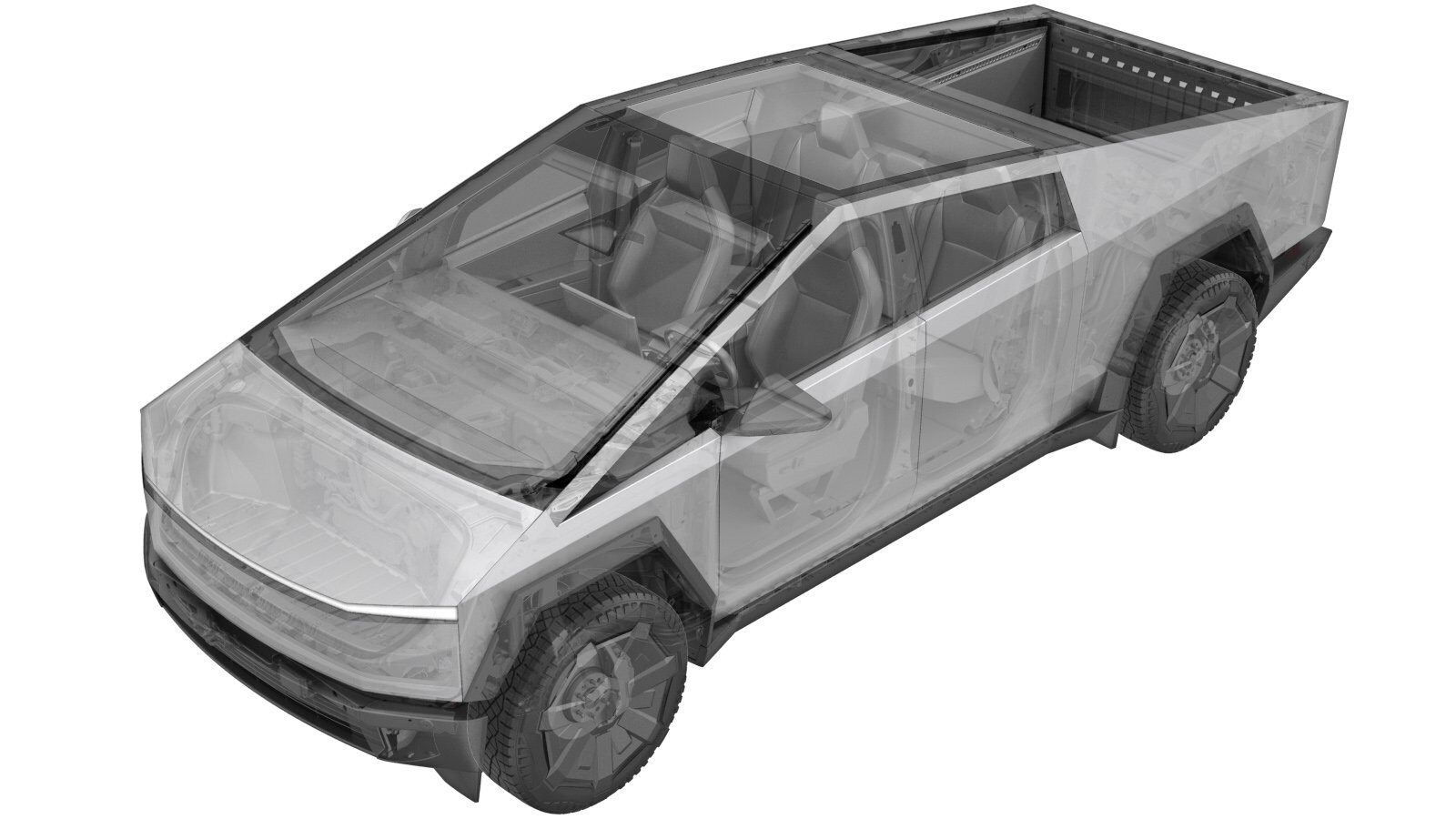
Fender Assembly - Front - LH (Remove and Install)
 Correction code
1010025081
FRT
0.66
NOTE: Unless otherwise explicitly stated in the procedure, the above correction code and FRT reflect all of the work required to perform this procedure, including the linked procedures. Do not stack correction codes unless explicitly told to do so.
NOTE: See Flat Rate Times to learn more about FRTs and how they are created. To provide feedback on FRT values, email ServiceManualFeedback@tesla.com.
NOTE: See Personal Protection to make sure wearing proper PPE when performing the below procedure.
NOTE: See Ergonomic Precautions for safe and healthy working practices.
Correction code
1010025081
FRT
0.66
NOTE: Unless otherwise explicitly stated in the procedure, the above correction code and FRT reflect all of the work required to perform this procedure, including the linked procedures. Do not stack correction codes unless explicitly told to do so.
NOTE: See Flat Rate Times to learn more about FRTs and how they are created. To provide feedback on FRT values, email ServiceManualFeedback@tesla.com.
NOTE: See Personal Protection to make sure wearing proper PPE when performing the below procedure.
NOTE: See Ergonomic Precautions for safe and healthy working practices.
Warning
This procedure is a DRAFT.
Although it has been validated, Warnings and Cautions might be missing. Follow safety
requirements and use extreme caution when working on or near High Voltage systems and
components.
Remove
- Open the LH doors and lower the LH windows.
- Remove the rear underhood apron. See Underhood Apron - Rear (Remove and Install).
- Remove the frunk assembly. See Frunk Assembly (Remove and Install).
- Remove the LH cantrail. See Trim - Cantrail - Roof Rail - LH (Remove and Install).
-
Release the clips (x11) and datums
(x3) that attach the LH front fender flare cover to the vehicle, disconnect the camera
electrical connector, and then remove the cover from the vehicle.
CAUTIONThe camera harness is very short. Make sure excess force is not exerted on the harness.NoteRelease all the clips before disconnecting the camera connector.
-
Remove the clips (x10) that attach the
LH front wheel liner to the fender flare carrier, and then release the liner from the
carrier.
-
Remove the bolts (x6) that attach the
LH front fore fender flare carrier to the vehicle, release the connector lock and
disconnect the electrical connector, and then remove the carrier from the vehicle.
 6 Nm (4.4 lbs-ft)NoteThe LH front BLE module is slotted into the fender flare carrier and will be removed with the assembly after disconnecting the connector.TIpUse of the following tool(s) is recommended:
- 10 mm socket
-
Remove the bolts (x3) that attach the
LH front aft fender flare carrier to the vehicle, and then remove the carrier from the
vehicle.6 Nm (4.4 lbs-ft)TIpUse of the following tool(s) is recommended:
- 10 mm socket
-
Release the clips (x2) that attach the
harness to the LH front fender.
-
Remove the bolts (x3) that attach the
LH front fender to the A-pillar.30 Nm (22.1 lbs-ft)TIpUse of the following tool(s) is recommended:
- 13 mm socket
-
Remove the bolts (x2) that attach the
LH front fender to the upper fender beam, and then remove the fender from the
vehicle.30 Nm (22.1 lbs-ft)NoteOpen and close front door as needed for clearance.NotePlace the fender on a padded surface.TIpUse of the following tool(s) is recommended:
- 13 mm socket
Install
-
Position the LH front fender onto the vehicle, and then install the bolts (x2) that
attach the fender to the upper fender beam.30 Nm (22.1 lbs-ft)NoteOpen and close front door as needed for clearance.NotePlace the fender on a padded surface.TIpUse of the following tool(s) is recommended:
- 13 mm socket
-
Install the bolts (x3) that attach the LH front fender to the A-pillar.30 Nm (22.1 lbs-ft)TIpUse of the following tool(s) is recommended:
- 13 mm socket
-
Install the clips (x2) that attach the harness to the LH front fender.
-
Position the LH front aft fender flare carrier to the vehicle, and then install the
bolts (x3) that attach the carrier to the vehicle.6 Nm (4.4 lbs-ft)TIpUse of the following tool(s) is recommended:
- 10 mm socket
-
Position the LH front fore fender flare carrier to the vehicle, connect the
electrical connector and engage the connector lock, and then install the bolts (x6) that
attach the carrier to the vehicle.6 Nm (4.4 lbs-ft)NoteMake sure the LH front BLE module is accessible.TIpUse of the following tool(s) is recommended:
- 10 mm socket
-
Install the clips (x10) that attach the LH front wheel liner to the fender flare
carrier.
-
Position the LH front fender flare cover to the vehicle, connect the camera
electrical connector, and then secure the clips (x11) and datums (x3) that attach the
cover to the vehicle.
CAUTIONThe camera harness is very short. Make sure excess force is not exerted on the harness.NoteReplace any missing or damaged clips.
- Install the LH cantrail. See Trim - Cantrail - Roof Rail - LH (Remove and Install).
- Install the frunk assembly. See Frunk Assembly (Remove and Install).
- Install the rear underhood apron. See Underhood Apron - Rear (Remove and Install).
- Close the powered frunk.
- Close the LH rear door.
-
Use the vehicle touchscreen to place
the vehicle into Service Mode.
NoteTouch Controls > Software, and then touch and hold "Cybertruck" for 2 seconds, and release. Use the screen keyboard to type "service" into dialog box, and then touch the OK button. Touch the "X" at the upper left corner to exit "Service Settings" dialogue box.
-
Unlock the vehicle gateway.
NoteAfter vehicle has been put into "Service Mode", place key card on center console to turn on drive rails. Hold down the brake pedal while keep pressing right hand signal button simultaneously for at least 10 seconds. "GTW UNLOCKING" should pop up on the UI right next to the VIN during these 10 seconds. Once the gateway is unlocked, "GTW UNLOCKED 5400" will be displayed on the UI next to the VIN. The gateway will remain unlocked for 90 minutes. Follow steps on Toolbox article #5582900 for any additional information.
-
Clear camera calibration via Service
UI.
NoteIn Service mode, navigate to Driver Assist > Cameras > Clear Camera Calibration > Camera Input > Forward Facing and press run.
-
Exit Service Mode.
NoteNavigate to Controls > Software, and then select Exit Service Mode button.
- Raise the front windows and close the LH front door.