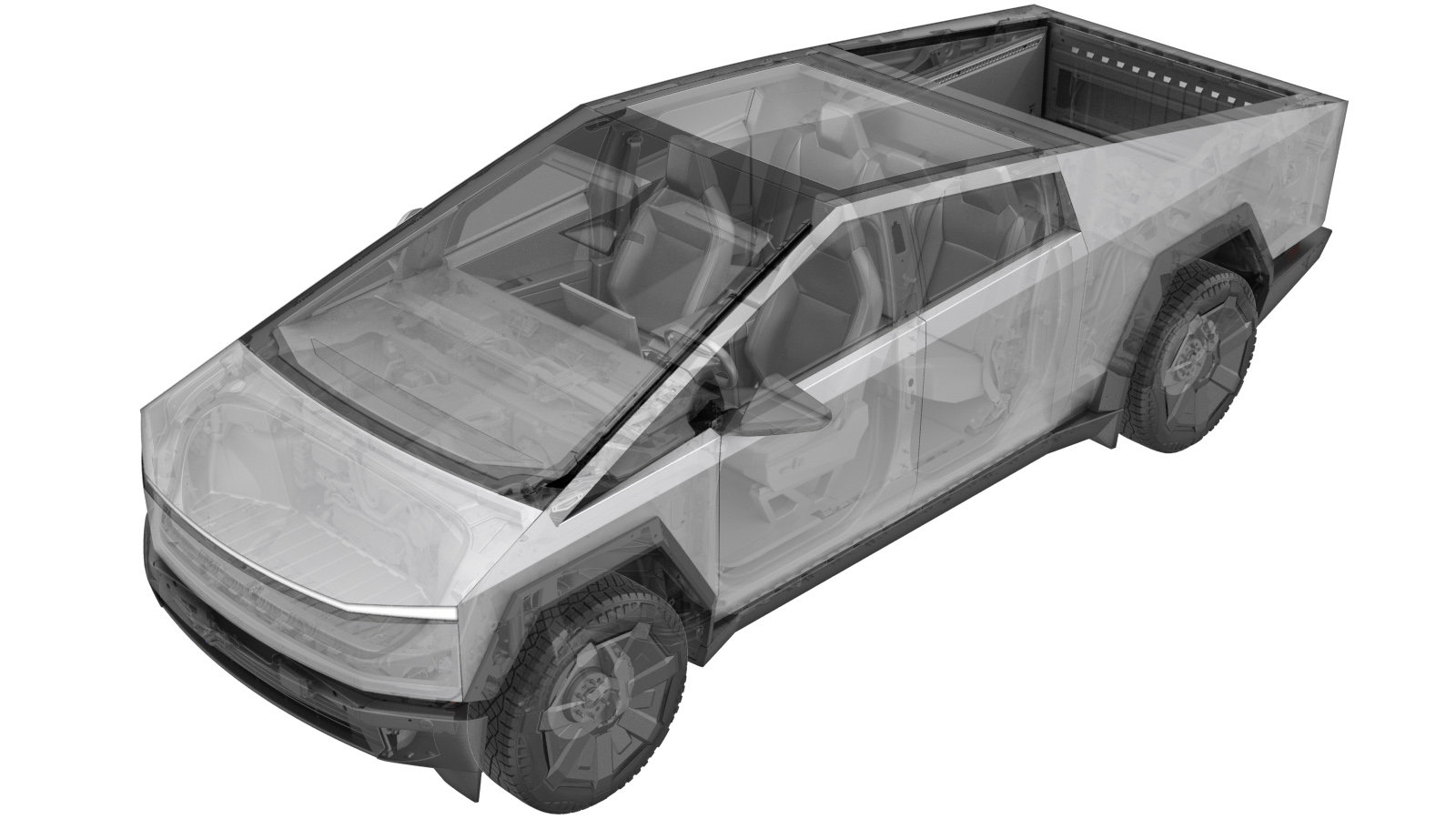
Tire Rotation and Balance with Automatic TPMS Learn (Rebalance)
 Correction code
34020505,
34020305
FRT 0.750.75
NOTE: Unless
otherwise explicitly stated in the procedure, the above correction code and
FRT reflect all of the work required to perform this procedure, including
the linked procedures. Do
not stack correction codes unless explicitly told to do so.
NOTE: See Flat Rate Times to learn more about FRTs and how
they are created. To provide feedback on FRT values, email ServiceManualFeedback@tesla.com.
NOTE: See Personal Protection
to make sure wearing proper PPE when performing the below procedure.
NOTE: See Ergonomic Precautions for safe and
healthy working practices.
- 2025-10-13: Added FRT and CCs
- Raise and support the vehicle. See Raise Vehicle - 2 Post Lift.
-
Determine rotation pattern
NoteVerify if tires are offset or directional, If non-directional and tires all are same size then move front tires to rear on opposite sides, then move rear tires to front, If non-directional and tires are different sizes then move LH to RH, Do not move front to rear, If directional tires then move front to rear, Do not move LH to RH
- Remove all 4 wheels. See Wheel Assembly (Remove and Install).
-
Remove wheel weights
-
Install tire and wheel assembly onto
balancer
Note1x 6-lug wheel flange, Position wheel onto spindle shaft then secure wheel using flange, If 6-lug wheel flange unavailable use 216mm Blue Hunter centering cone adapter
-
Verify tire pressure is set
NoteSet to specification if necessary, Refer to the "Tire and Loading Information" label located on the driver side B-pillar, re-install valve stem cap
-
Input wheel dimensions into balancer
machine
NoteIf manual input necessary
-
Spin wheel to check balance
-
Install weights in positions indicated
by machine
-
Perform check spin
-
Remove tire and wheel assembly from
balancer
Note1x 6-lug wheel flange, Remove flange then remove wheel from spindle shaft
- Repeat step 4 through step 11 for the remaining wheels.
- Install all 4 wheels. See Wheel Assembly (Remove and Install).
- Remove the vehicle from the lift. See Raise Vehicle - 2 Post Lift.