HV Connector - Busbar - Charge Port (Long Range) (Remove and Install)
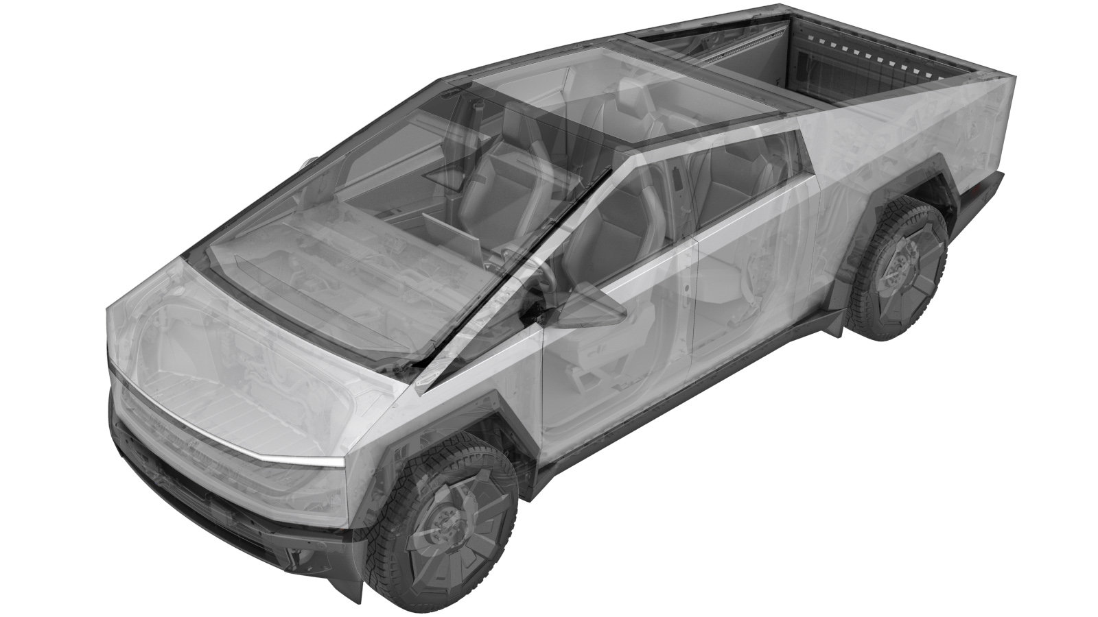 Correction code
44500300301
1.08
NOTE: Unless
otherwise explicitly stated in the procedure, the correction code and its
associated FRT reflect all of the work required to perform this procedure,
including the linked procedures. Do not stack correction
codes unless explicitly told to do so.
NOTE: See Flat Rate Times to
learn more about FRTs and how they are created.
NOTE: See Personal Protection to make
sure you are wearing proper PPE when performing the procedure below.
NOTE: See Ergonomic Precautions for safe and healthy
working practices.
Correction code
44500300301
1.08
NOTE: Unless
otherwise explicitly stated in the procedure, the correction code and its
associated FRT reflect all of the work required to perform this procedure,
including the linked procedures. Do not stack correction
codes unless explicitly told to do so.
NOTE: See Flat Rate Times to
learn more about FRTs and how they are created.
NOTE: See Personal Protection to make
sure you are wearing proper PPE when performing the procedure below.
NOTE: See Ergonomic Precautions for safe and healthy
working practices.
High Voltage Awareness Care Pointsfor additional glove and safety information.
- 2025-06-21: Released new procedure.
- Open the LH front door and lower the LH front window.
- Raise and support the vehicle. See Raise Vehicle - 2 Post Lift.
- Open the tailgate.
- Remove the bed floor assembly. See Bed Floor Assembly (Long Range) (Remove and Install).
- Disconnect MV power. See Mid-Voltage Power (Disconnect and Connect) (Modify).
-
Verify operation of multimeter
NoteSet multimeter to DC voltage, Confirm multimeter is properly measuring voltage by testing MV battery, Touch lightly and do not damage terminals
-
Raise vehicle fully
NoteSet to a comfortable working height, Lower to locks, Ensure locks engage on both sides to prevent tilting
- Remove the rear skid plate. See Skid Plate - Rear (Remove and Install).
-
Remove all items from pockets and ensure not wearing metal items
-
Inspect HV insulating gloves
NoteCheck gloves for damage prior to use, Refer to service document TN-15-92-003
-
Put on HV insulating gloves and leather over gloves
-
Verify no HV - Install amp clamp to RDU HV harness
NoteVerify meter is zeroed out before performing measurement, Measure single cable. Verify ammeter is installed in correct direction. If current > 0.5A do not proceed with disconnecting HV connector. In this case, start vehicle electrical isolation again to make sure that all was properly shut down. Escalate for assistance as requiredIf current < 0.5A, Ok to disconnect and check voltage at HV plug on the battery side.Release locking tab and rotate the release lever up to disengage the connector, Release harness clip, Do not force the release lever up, Ensure the alignment tabs on the RDU header are not damagedMake sure to wear PPE (HV gloves, safety glasses) when working on high voltage component, Measure B+ to Ground, B- to Ground, B+ to B-, If voltage is greater than 10V, Pack contactors are not open or welded, Stop work and reach out to Service Engineering
-
Secure RDU header connector to ancillary
Note1x connector, Verify lever is in the upright and open position, Carefully seat connector and allow lever to engage, Fully secure lever and verify red tab is locked, Do not damage any pins
-
Lower vehicle until tires are touching the ground
NoteRaise lift off locks, then hold lock release lever to keep locks free while vehicle is lowered
-
Remove bolt securing busbar HV connector lid
Note1x bolt, EP10, 9 Nm
-
Remove bolts securing HV connector to DC FC header
Note2x bolts, 10mm, 9 Nm
-
Release HV connector from DC FC header
Note1x connector, Use inflatable airbag to suspend busbar assembly above ancillary assembly
-
Raise CP busbar connector
Note2x inflatable bags, Install bags, Do not open tonneau to prevent damage
-
Remove screws securing HV connector to CP busbars
Note2x screws, T20, 1.5 Nm, Position mirror as needed
-
Remove HV connector from CP busbars
NoteGently pry between orange clips and primary heat sink, Pull evenly
-
Position HV connector onto CP busbars
NotePush evenly, Make sure orange clips are flush with primary heat sink
-
Install screws securing HV connector to CP busbars
Note2x screws, T20, 1.5 Nm, Position mirror as needed
-
Clean HV connector contact surface of residual Penetrox
NoteAllow 1 minute dry time after removing Penetrox, New busbar comes with Penetrox applied to HV connector
-
Apply Penetrox onto HV connector joints
NoteApply 2 drops of Penetrox A-13 about 5mm in diameter to either side of the hole on both leads, Spread evenly to verify the contact surface is fully covered
-
Clean busbar HV connector contact surface of residual Penetrox
NoteAllow 1 minute dry time after removing Penetrox, It is necessary to clean HV connector during re-use of busbar
-
Lower CP busbar connector
Note2x inflatable bags, Remove bags, Do not open tonneau to prevent damage
-
Position busbar connector and lower onto HV header
NoteRelease bungee cord
-
Install bolts securing charge port busbar kit to HV Header
Note2x bolts, 10mm, 9 Nm
-
Perform Hioki resistance test at each HV joint from HV busbar lead to bolt head
Note2x HV joints, When using Hioki tester, verify the meter has been properly adjusted and set prior to usageThe acceptable resistance is between 0.050 mΩ (50 μΩ) and 0.195 mΩ (195 μΩ).If the resistance is greater than 0.195 mΩ (195 μΩ), stop work and escalate the Toolbox session.If the resistance is lower than 0.050 mΩ (50 μΩ), reposition the probes and measure again.If the resistance is repeatedly between 0.00 mΩ and 0.050 mΩ (50 μΩ), hioki test passed, proceed to next step
-
Install bolt securing busbar HV connector lid
Note1x bolt, EP10, 9 Nm
- Reconnect MV power. See Mid-Voltage Power (Disconnect and Connect) (Modify).
- Install the bed floor assembly. See Bed Floor Assembly (Long Range) (Remove and Install).
- Install the rear underhood apron. See Underhood Apron - Rear (Remove and Install).
- Close the tonneau cover.
- Close the tailgate.
- Install the rear skid plate. See Skid Plate - Rear (Remove and Install).
- Remove the vehicle from the lift. See Raise Vehicle - 2 Post Lift.
- Raise the LH front window and close the LH front door.