Cover - Phase Out - Inverter - Front Drive Unit (Remove and Install)
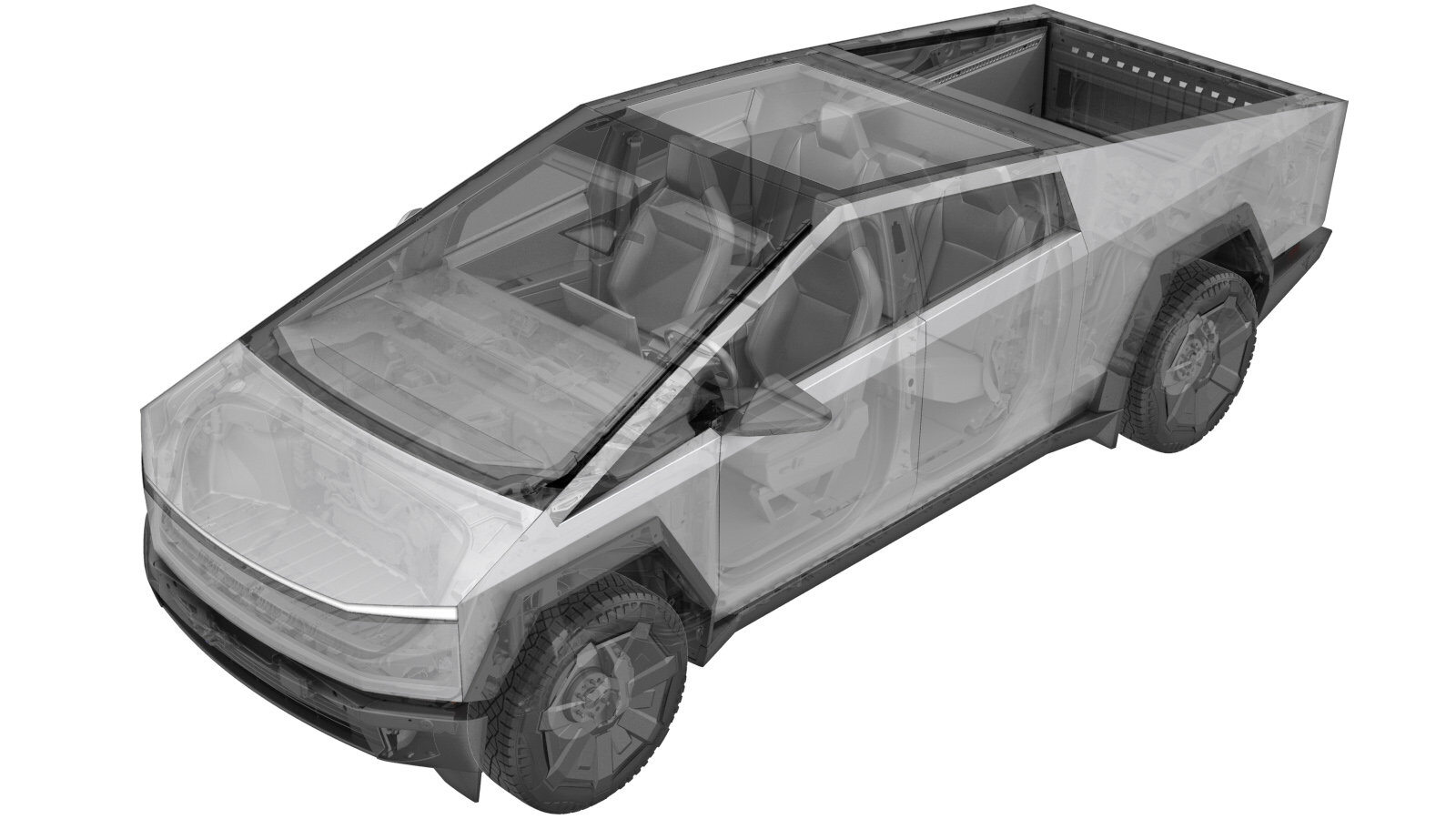 Correction code
3920048011
3920048012
FRT
0.60
NOTE: Unless
otherwise explicitly stated in the procedure, the above correction code and
FRT reflect all of the work required to perform this procedure, including
the linked procedures. Do
not stack correction codes unless explicitly told to do so.
NOTE: See Flat Rate Times to learn more about FRTs and how
they are created. To provide feedback on FRT values, email ServiceManualFeedback@tesla.com.
NOTE: See Personal Protection
to make sure wearing proper PPE when performing the below procedure.
NOTE: See Ergonomic Precautions for safe and
healthy working practices.
Correction code
3920048011
3920048012
FRT
0.60
NOTE: Unless
otherwise explicitly stated in the procedure, the above correction code and
FRT reflect all of the work required to perform this procedure, including
the linked procedures. Do
not stack correction codes unless explicitly told to do so.
NOTE: See Flat Rate Times to learn more about FRTs and how
they are created. To provide feedback on FRT values, email ServiceManualFeedback@tesla.com.
NOTE: See Personal Protection
to make sure wearing proper PPE when performing the below procedure.
NOTE: See Ergonomic Precautions for safe and
healthy working practices.
Remove
- Open the LH front door and lower the LH front window.
- Place the vehicle into Service Mode. See Service Mode.
- Raise and support the vehicle. See Raise Vehicle - 2 Post Lift.
- Remove the rear underhood apron. See Underhood Apron - Rear (Remove and Install).
- Disconnect MV power. See Disconnect MV Power (Modify).
- Perform Vehicle HV Disablement procedure. See Vehicle HV Disablement Procedure (Test/Adjust).
-
Remove the bolts (x8) and clips (x6)
that attach the mid aeroshield to the vehicle, and then remove the aeroshield from the
vehicle.
TIpUse of the following tool(s) is recommended:
- 15 mm socket
- 13 mm socket
- 10 mm socket
- Remove the front aeroshield. See Aeroshield - Front (Remove and Install).
-
Remove and discard the label from the
phase out cover.
-
Remove the bolts (x2) that attach the
phase out cover to the vehicle.
TIpUse of the following tool(s) is recommended:
- External Torx Plus EP10
-
Use a plastic trim tool to remove the
phase out cover from the vehicle.
Install
- Inspect the O-rings on the new phase out cover. If the phase out cover O-rings are damaged, then replace with a new unit.
-
Install the phase out cover into the
vehicle.
-
Install the bolts (x2) that attach the phase out cover to the vehicle.
 5 Nm (3.7 lbs-ft) +20 degTIpUse of the following tool(s) is recommended:
- External Torx Plus EP10
-
Install a new label onto the phase out cover.
- Install the front aeroshield. See Aeroshield - Front (Remove and Install).
- Lower the vehicle until the tires are touching the ground.
- Reconnect MV power. See Disconnect MV Power (Modify).
- Install the rear underhood apron. See Underhood Apron - Rear (Remove and Install).
- Remove the vehicle from the lift. See Raise Vehicle - 2 Post Lift.
- Raise the LH front window and close the LH front door.