Supermanifold (Remove and Replace)
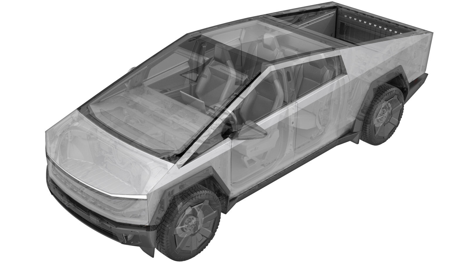 Correction code
1840114072
FRT
1.32
NOTE: Unless
otherwise explicitly stated in the procedure, the above correction code and
FRT reflect all of the work required to perform this procedure, including
the linked procedures. Do
not stack correction codes unless explicitly told to do so.
NOTE: See Flat Rate Times to learn more about FRTs and how
they are created. To provide feedback on FRT values, email ServiceManualFeedback@tesla.com.
NOTE: See Personal Protection
to make sure wearing proper PPE when performing the below procedure.
NOTE: See Ergonomic Precautions for safe and
healthy working practices.
Correction code
1840114072
FRT
1.32
NOTE: Unless
otherwise explicitly stated in the procedure, the above correction code and
FRT reflect all of the work required to perform this procedure, including
the linked procedures. Do
not stack correction codes unless explicitly told to do so.
NOTE: See Flat Rate Times to learn more about FRTs and how
they are created. To provide feedback on FRT values, email ServiceManualFeedback@tesla.com.
NOTE: See Personal Protection
to make sure wearing proper PPE when performing the below procedure.
NOTE: See Ergonomic Precautions for safe and
healthy working practices.
- 2024-10-7: Added step to add refrigerant evacuation and recharge correction codes as needed.
Remove
- This procedure requires refrigerant evacuation and recharge. Add the specific evacuation and recharge correction as needed.
- Prepare the A/C machine.
- Open the LH front door and lower the LH front window.
- Place the vehicle into Service Mode. See Service Mode.
- Unlock the vehicle Gateway. See Gateway (Unlock).
- On the vehicle touchscreen, navigate to .
-
Tap Start Thermal Fill Drain (Coolant +
Refrigerant ) and allow the routine to complete.
NoteMake sure the routine is successful.
- Remove the rear underhood apron. See Underhood Apron - Rear (Remove and Install).
- Disconnect MV power. See Disconnect MV Power (Modify).
- Raise and support the vehicle. See Raise Vehicle - 2 Post Lift.
- Perform Vehicle HV Disablement procedure. See Vehicle HV Disablement Procedure (Test/Adjust).
- Remove the front aero shield. See Aeroshield - Front (Remove and Install).
- Place a coolant catcher below the RH front of the vehicle.
- Lower the vehicle until the tires are touching the ground.
- Recover the A/C refrigerant. See A/C Refrigerant (Recovery and Recharge).
- Remove the frunk assembly. See Frunk Assembly (Remove and Install).
-
Remove the bolts (x2) that attach the
supermanifold to the megabeam.
 33 Nm (24.3 lbs-ft)NoteBreak the bolts free, and then remove by hand to avoid tool jamming.NoteSupport the supermanifold from underneath. Lower supermanifold until it resting on the HVAC case.TIpUse of the following tool(s) is recommended:
- 15 mm deep socket
-
Release the hose clips, and then
disconnect the powertrain bypass hose, the radiator outlet hose, and the radiator inlet
hose from the supermanifold.
NoteThis will drain the coolant reservoir.
-
Release the hose clip, disconnect the
radiator outlet hose from the radiator, and then remove the hose from the vehicle.
NotePlug the radiator after removing the hose.
-
Disconnect the supermanifold harness
electrical connector.
-
Disconnect the chiller to battery
hose, the powertrain supply hose, and the chiller to battery hose from the
supermanifold.
Notex3 spring clip; x2 electrical connectorsNoteDo not push down on red tab. Pull the red tab to disengage the lock, and then pull again to release the electrical connector.NotePull the supermanifold forward to access the spring clips and electrical connectors.
-
Remove the bolt that attaches the
remote brake fluid reservoir to the vehicle, lift the reservoir upward to release the
datum, and then position the reservoir aside.
CAUTIONMake sure the reservoir does not tip over while maneuvering.TIpUse of the following tool(s) is recommended:
- 10 mm socket
-
Release the connector lock, and then
disconnect the A/C compressor logic electrical connector.
NoteDo not push down on red tab. Pull to disengage lock, and then pull again to release the electrical connector.
-
Release the connector lock, and then
disconnect the A/C Compressor HV harness electrical connector from the A/C
Compressor.
NotePull the red locking tab away from the black lever, and then slide the black lever upwards.
-
Remove the bolt that attaches the A/C
compressor ground strap, and then release the harness edge clip once the ground is
free.7 Nm (5.2 lbs-ft)TIpUse of the following tool(s) is recommended:
- 10 mm socket
- Place a fender cover on the fan housing.
-
With an assistant supporting the A/C
compressor, remove the bolts (x3) that attach the A/C compressor to the megabeam, and
then gently place the A/C compressor assembly down.5 Nm (3.7 lbs-ft)NoteCarefully maneuver the A/C compressor towards the front of the vehicle and under the megabeam.CAUTIONAvoid straining the MV or HV harnesses.TIpUse of the following tool(s) is recommended:
- 10 mm socket
-
Remove the nuts (x2) that attach the
refrigerant suction and discharge lines from the A/C compressor, and then remove the
lines from the A/C compressor.22 Nm (16.2 lbs-ft)NoteMake sure that the washers do not remain on the A/C compressor.TIpUse of the following tool(s) is recommended:
- 13 mm socket
- Remove the A/C compressor from the vehicle.
-
Release the tabs (x5) that attach the
NVH cover to the old A/C compressor, and then remove the NVH cover from the
compressor.
-
Protect the LP and HP opening ports on
the AC compressor with masking tape.
-
Reset the A/C compressor oil
level.
NoteZero scale before use.NoteLocate manufacturer label on compressor, and then note the "Dry Weight" from the label.NotePlace compressor on the scale, and then add RB100EV POE oil until the scale reads the value equal to dry weight plus 250g. For example: (Dry weight = 7000g. Add oil until scale reads 7250g).
-
Position the NVH cover onto the A/C
compressor, and then engage the tabs (x5).
NoteMake sure that the NVH cover is fully secured to the compressor.
-
Install the A/C flush adapters on the
A/C manifold to A/C compressor lines.22 Nm (16.2 lbs-ft)TIpUse of the following tool(s) is recommended:
- 13 mm socket
NoteInstall the flush adapters onto the suction and discharge lines on the A/C compressor side.NoteLeave the seal washers on the A/C manifold line.NoteInspect O-rings and replace them, if damaged.NoteUse 13 mm nuts from the A/C compressor to secure the flush adapters. -
Perform the A/C System Flush
procedure.
NoteSystem flush procedure runs for approximately 90 minutes. Minimum of 3200g of refrigerant needed in the tank to run system flush procedure. On the A/C machine main menu, select > Manual > Flushing Kit. Enter 25 min vacuum time > Enter > Connect and open couplers > Enter.NoteA/C machine will perform multiple flush cycles.NoteAllow process to complete.
-
Remove the A/C flush adapters from the
supermanifold to the compressor A/C line assembly.
TIpUse of the following tool(s) is recommended:
- 13 mm socket
-
Remove the nut that attaches the Penta
HVAC line assembly to the supermanifold plate.36 Nm (26.5 lbs-ft)TIpUse of the following tool(s) is recommended:
- 13 mm deep socket
-
Remove the A/C line from the
supermanifold.
Notex1 bolt, 13 mm, 22 Nm; x1 bolt, 10 mm, 8 NmNoteRemove the bolt at the supermanifold, and then mounting bracket bolt near the MV battery.NoteRemove the A/C line assembly from the supermanifold.NoteMake sure that no washers remain on the supermanifold.
-
With assistance, remove the
supermanifold from the vehicle.
NoteRotate the supermanifold counterclockwise under the megabeam.NoteSupport from underneath and at the reservoir.
Install
-
Replace the seal washers (x5) to the
Penta HVAC line on the A/C manifold side.
NoteLubricate the seal washers with RB100EV POE oil.
-
With assistance, install the
supermanifold to the vehicle.
NoteRotate the supermanifold counterclockwise under the megabeam.NoteSupport from underneath and at reservoir.NoteAlign penta HVAC line.
-
Secure the chiller to battery hose,
the powertrain supply hose, and the chiller to battery hose to the supermanifold.
Notex3 spring clip, x2 electrical connectors.NoteEngage the locking tabs.NoteMake sure that all hoses are fully engaged with a push-pull-push test.
-
Install the nut that attaches the
pentaline to the supermanifold.36 Nm (26.5 lbs-ft)TIpUse of the following tool(s) is recommended:
- 13 mm deep socket
NoteMake sure that good alignment of pipes before tightening the nut. -
Install the bolts (x2) that attach the
supermanifold to the megabeam.33 Nm (24.3 lbs-ft)TIpUse of the following tool(s) is recommended:
- 15 mm deep socket
NoteStart the bolts by hand. -
Connect the radiator outlet hose to
the radiator, and then secure the hose clip.
NotePerform a push-pull-push test to make sure the hose is fully engaged.
-
Secure the powertrain bypass hose, the
radiator outlet hose, and the radiator inlet hose to the supermanifold.
Notex3 spring clipsNoteMake sure that all hoses are fully engaged with a push-pull-push test.
-
Connect the supermanifold electrical
connector.
-
Replace the seal washers (x2) for the
supermanifold to compressor A/C line on the supermanifold side.
NoteLubricate the seal washers with RB100EV POE oil.
-
Install the A/C manifold line assembly
to the supermanifold.
Notex1 bolt, 13 mm, 22 Nm; x1 bolt, 10 mm, 8 NmNoteInstall new washer seals.NoteInstall the manifold to the supermanifold, and then secure the bracket near the MV battery.
-
Perform the A/C Vacuum and Run Leak
Test. See A/C Refrigerant (Recovery and Recharge).
NoteSet the vacuum time to 20 minutes.
- Perform the cooling system vacuum refill procedure. See Cooling System (Vacuum Refill).
- Perform the A/C refrigerant recharge. See A/C Refrigerant (Recovery and Recharge).
- Reconnect MV power. See Disconnect MV Power (Modify).
-
Reinstall vehicle software.
NoteTouch Service Mode UI > Software Reinstall > Reinstall.NoteVehicle software installation will begin immediately.
- On the vehicle touchscreen, navigate to .
- Tap Start Coolant Air Purge, tap Run, and allow the routine to complete.
- Inspect the coolant level and top off as necessary.
- Perform the A/C performance tests. See A/C Refrigerant (Recovery and Recharge).
- Exit Service Mode. See Service Mode.
- Install the frunk. See Frunk Assembly (Remove and Install).
- Remove the vehicle from the lift. See Raise Vehicle - 2 Post Lift.
- Raise the LH front window and close the LH front door.