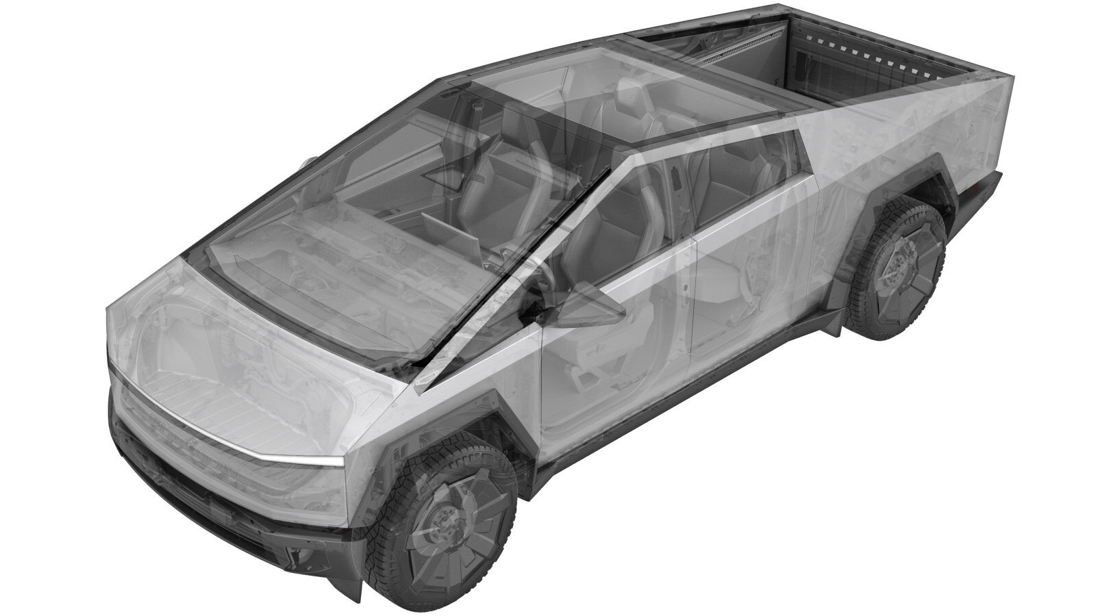
Cover - Pyro Access - HV Battery (Remove and Install)
 Correction code
1601070061
1601070062
FRT
0.60
NOTE: Unless
otherwise explicitly stated in the procedure, the above correction code and
FRT reflect all of the work required to perform this procedure, including
the linked procedures. Do
not stack correction codes unless explicitly told to do so.
NOTE: See Flat Rate Times to learn more about FRTs and how
they are created. To provide feedback on FRT values, email ServiceManualFeedback@tesla.com.
NOTE: See Personal Protection
to make sure wearing proper PPE when performing the below procedure.
NOTE: See Ergonomic Precautions for safe and
healthy working practices.
- 2025-11-10: VOSS fittings are reusable. Removed steps that instructed to discard fittings.
- 2024-05-01: Added steps to remove/install the SCUBA lines.
Only technicians who have been trained in High Voltage Awareness and have completed all required certification courses (if applicable) are permitted to perform this procedure. Proper personal protective equipment (PPE) and insulating HV gloves with a minimum rating of class 0 (1000V) must be worn at all times a high voltage cable, busbar, or fitting is handled. Refer to Tech Note TN-15-92-003, High Voltage Awareness Care Points
for additional glove and safety information.
Remove
- Move the vehicle to a 2 post lift. See Raise Vehicle - 2 Post Lift.
- Open the LH front door and lower the LH front window.
- Open the powered frunk.
- Remove the rear underhood apron. See Underhood Apron - Rear (Remove and Install).
- Disconnect MV power. See Disconnect MV Power (Modify).
- Fully raise the vehicle.
-
Remove the clips (x6) and bolts (x10)
that attach the mid aeroshield to the vehicle, and then remove the aeroshield from the
vehicle.
TIpUse of the following tool(s) is recommended:
- 15 mm socket
- 13 mm socket
- 10 mm socket
-
Disconnect the SCUBA lines.
 8 Nm (5.9 lbs-ft)TIpUse of the following tool(s) is recommended:
- 12 mm socket
- Perform Vehicle HV Disablement procedure, but do not reintegrate HV power yet. See Vehicle HV Disablement Procedure (Test/Adjust).
-
Remove the bolts (x4) that attach the
pyro fuse access cover to the HV battery.
 10 Nm (7.4 lbs-ft)TIpUse of the following tool(s) is recommended:
- External Torx E10 5-Lobe
Install
-
Position the pyro fuse access cover
onto the HV battery, and then install the bolts (x4) that attach the cover to the HV
battery.
 10 Nm (7.4 lbs-ft)CAUTIONMake sure the seal is fully seated and undamaged.TIpUse of the following tool(s) is recommended:
- External Torx E10 5-Lobe
- Integrate HV power. See Vehicle HV Disablement Procedure (Test/Adjust).
- Remove leather over gloves and HV insulating gloves.
-
Install the SCUBA lines.
 8 Nm (5.9 lbs-ft)NoteRemove the plastic cap from the VOSS fitting, and then press the air line into the fitting until the mark aligns with the top of the fitting. Verify the air line is properly secured by performing push-pull-push test.TIpUse of the following tool(s) is recommended:
- 12 mm socket
-
Position the mid aeroshield to the
vehicle, and then install the bolts (x10) and clips (x6) that attach the aeroshield to
the vehicle.
 42 Nm (31.0 lbs-ft)
 28 Nm (20.6 lbs-ft)
 6 Nm (4.4 lbs-ft)NoteApply Loctite 222 onto the bolts before installing.NoteThe 15 mm bolts (x3) are torqued to 42 Nm, the 13 mm bolts (x5) to 28 Nm, and the 10 mm bolts (x2) to 6 Nm.TIpUse of the following tool(s) is recommended:
- 15 mm socket
- 13 mm socket
- 10 mm socket
- Reconnect MV power. See Disconnect MV Power (Modify).
- Install the rear underhood apron. See Underhood Apron - Rear (Remove and Install).
- Connect a laptop with Toolbox 3 to the vehicle. See Toolbox 3 (Connect and Disconnect).
-
In Toolbox, perform the HV Battery
Leak Test routine.
- Click the Actions tab.
- Search for "Pressurise".
- Click Tesla Air Suspension Pressurise HV Pack.
- Click Run, and ensure the routine is successful.
- Disconnect Toolbox 3 and remove the laptop from the vehicle. See Toolbox 3 (Connect and Disconnect).
- Raise the LH front window and close the LH front door.
- Remove the vehicle from the lift. See Raise Vehicle - 2 Post Lift.