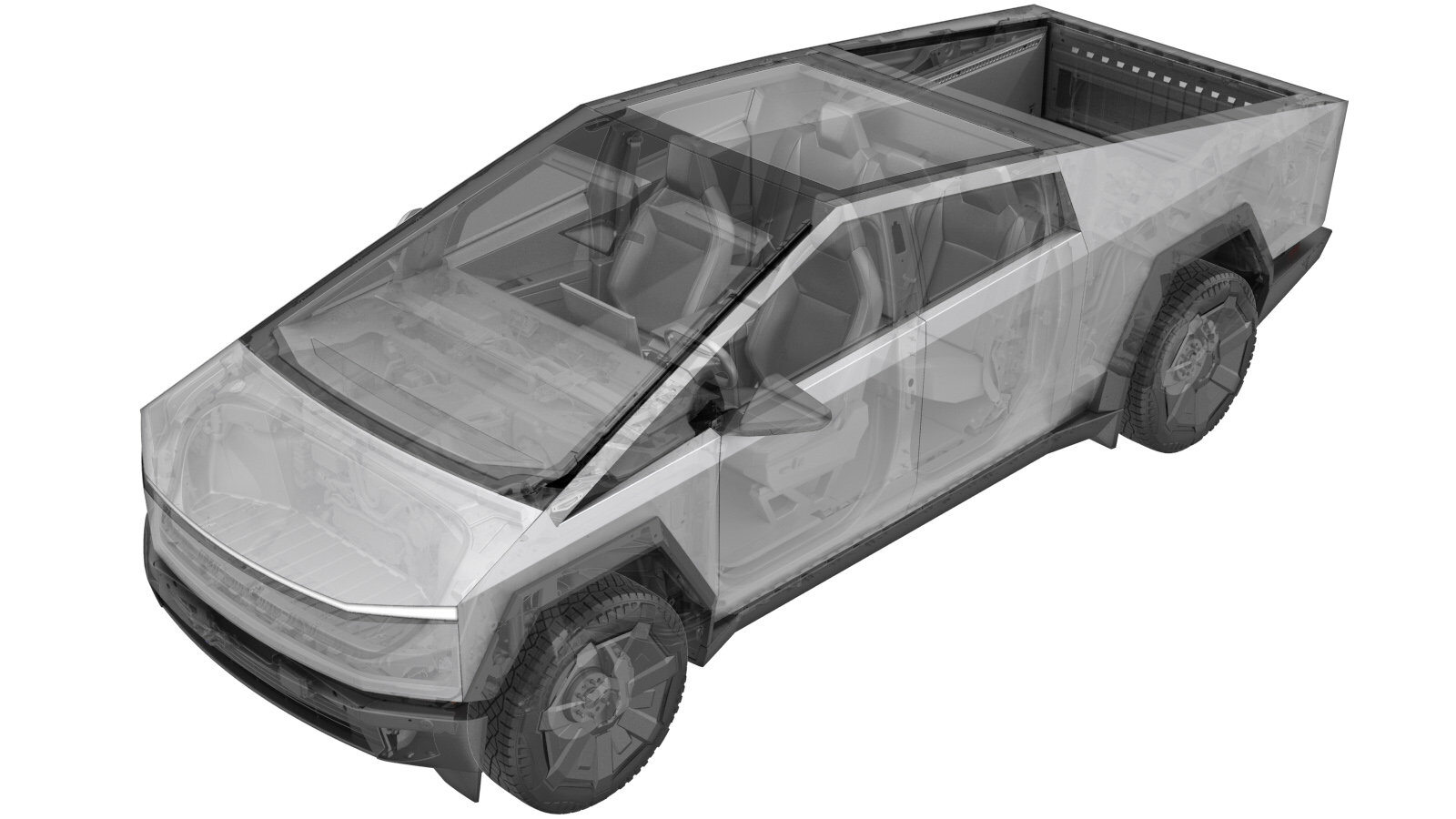
Fuse, 60A, 1000VDC, Eaton EVK22-60-T - Ancillary (Remove and Replace)
 Correction code
1630010191
1630010192
1601070121
1601070122
FRT
3.30
NOTE: Unless
otherwise explicitly stated in the procedure, the above correction code and
FRT reflect all of the work required to perform this procedure, including
the linked procedures. Do
not stack correction codes unless explicitly told to do so.
NOTE: See Flat Rate Times to learn more about FRTs and how
they are created. To provide feedback on FRT values, email ServiceManualFeedback@tesla.com.
NOTE: See Personal Protection
to make sure wearing proper PPE when performing the below procedure.
NOTE: See Ergonomic Precautions for safe and
healthy working practices.
- 2024-11-22: Added warning to NOT skip steps to remove the tonneau slats.
Remove
- Remove the ancillary cover. See Ancillary Cover (Remove and Install).
-
Inspect the HV insulating
gloves.
NoteCheck the gloves for damage prior to use. Refer to service document TN-15-92-003 for information on inspecting HV gloves.
-
Put on the HV insulating gloves and
leather over gloves.
-
Remove the fuse bolts (x2).
 6 Nm (4.4 lbs-ft)TIpUse of the following tool(s) is recommended:
- 8 mm socket (insulated)
-
Remove the fuse using a fuse
puller.
-
If grease was found around the inner perimeter of the DC FC header, use a disposable towel to wipe the grease off the header and the busbar connector.
NoteDo not allow the grease to contact the busbar HV mating surfaces.
Install
-
Install the fuse.
-
Install the fuse bolts (x2).
 6 Nm (4.4 lbs-ft)TIpUse of the following tool(s) is recommended:
- 8 mm socket (insulated)
-
Perform a Hioki measurement from the
fuse joint to the FCC harness terminal.
NotePerform a zero adjust to Hioki meter prior to testing.Note200𝜇Ω or less
-
Perform a Hioki measurement from the
fuse joint to the PCS harness terminal.
NotePerform zero adjust to Hioki meter prior to testing.Note200𝜇Ω or less
- Install the ancillary cover. See Ancillary Cover (Remove and Install).