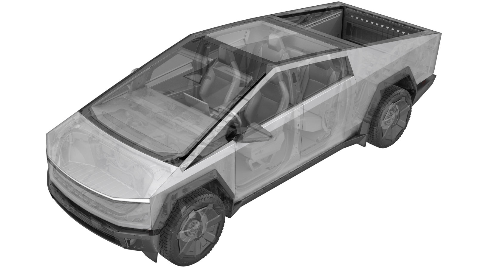
Fender Assembly - Front - LH (Remove and Replace)
 Correction code
1010025082
1010025092
FRT
0.66
NOTE: Unless
otherwise explicitly stated in the procedure, the above correction code and
FRT reflect all of the work required to perform this procedure, including
the linked procedures. Do
not stack correction codes unless explicitly told to do so.
NOTE: See Flat Rate Times to learn more about FRTs and how
they are created. To provide feedback on FRT values, email ServiceManualFeedback@tesla.com.
NOTE: See Personal Protection
to make sure wearing proper PPE when performing the below procedure.
NOTE: See Ergonomic Precautions for safe and
healthy working practices.
- 2025-11-19: Added note to pull C-pillar downward for access cantrail fasteners.
- Open LH doors and lower the LH windows.
- Open the powered frunk.
- Remove the rear underhood apron. See Underhood Apron - Rear (Remove and Install).
- Remove the frunk assembly. See Frunk Assembly (Remove and Install).
- Remove the LH underhood apron. See Underhood Apron - LH (Remove and Install).
-
Remove nut securing LH front outer cantrail
Note1x nut, 8mm, 4 Nm
-
Remove LH header seal
NoteSeal begins at front quarter glass and ends at C-pillar applique, Pull outwards to release
-
Remove screws securing LH cantrail
NotePull C-pillar applique down as required for accessNote8x screws, T20, 2.5 Nm
-
Remove LH roof rail trim
Note11x clips, Recommend assistance, Place on padded surface
-
Remove LH front fender flare cover
Note11x clips, 3x datums, 1x connector, Release all clips then repeater connector before removal, Camera harness is very short, Ensure excess force is not exerted on harness
-
Release LH front wheel liner from fender flare carrier
Note10x push clips
-
Remove LH front fore fender flare carrier
Note6x bolts, 10mm, 6 Nm, 1x connector, LH front BLE module is slotted into the fender flare carrier and will be removed with the assembly after disconnection, Release locking tab
-
Remove LH front aft fender flare carrier
Note3x bolts, 10mm, 6 Nm
-
Release harness from LH front fender
Note2x clips
-
Remove bolts securing LH front fender to A-pillar
Note3x bolts, 13mm, 30 Nm, Open and close door as required for access, Ratcheting wrench aids in access for removal
-
Remove bolts securing LH front fender onto upper fender beam
Note2x bolts, 13mm, 30 Nm
-
Remove LH front fender
NoteOpen and close front door as needed for clearance, Place on a padded surface
-
Remove LH fender baffle
Note3x clips
-
Install LH fender baffle
Note3x clips
-
Install LH front fender
NotePosition LH front fender onto vehicle for installation
-
Install bolts securing LH front fender onto upper fender beam
Note2x bolts, 13mm, 30 Nm
-
Install bolts securing LH front fender to A-pillar
Note3x bolts, 13mm, 30 Nm, Open and close door as required for access
-
Install harness onto LH front fender
Note2x clips
-
Install LH Front aft fender flare carrier
Note3x bolts, 10mm, 6 Nm
-
Install LH Front fore fender flare carrier
Note6x bolts, 10mm, 6 Nm, 1x connector, Ensure BLE connector is accesible, Engage locking tab
-
Install clips securing LH front wheel liner to fender flare carrier
Note10x push clips
-
Install LH front fender flare cover
Note11x clips, 3x datums, 1x connector, Make camera connection before flare installation, Ensure excess force is not exerted on camera harness, Replace any missing or damaged clips
-
Install LH roof rail trim
Note11x clips, Replace any missing or damaged clips, Recommend assistance
-
Install screws securing LH cantrail
Note8x screws, T20, 2.5 Nm
-
Install LH header seal
NoteStart from front quarter glass working seal into groove by pushing inwards
-
Install nut securing LH front outer cantrail
Note1x nut, 10mm, 4 Nm
- Install the LH underhood apron. See Underhood Apron - LH (Remove and Install).
- Install the frunk assembly. See Frunk Assembly (Remove and Install).
- Install the rear underhood apron. See Underhood Apron - Rear (Remove and Install).
- Close the powered frunk.
- Close the LH rear door.
- Place the vehicle into Service Mode. See Service Mode.
- Unlock the vehicle Gateway. See Gateway (Unlock).
-
Clear camera calibration via Service UI
NoteVia UI > Driver Assist > Cameras > Clear Camera Calibration > Camera Input > ForwardFacing > Run
- Exit Service Mode. See Service Mode.
- Raise the LH windows and close the LH front door.