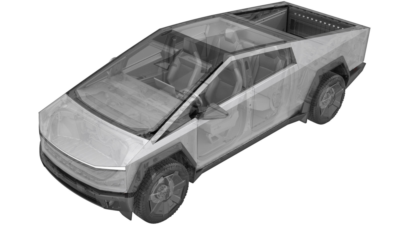
Coil, EXV4.5/VCV - Supermanifold (Remove and Replace)
 Correction code
1840010092
0.30
NOTE: Unless
otherwise explicitly stated in the procedure, the above correction code and
FRT reflect all of the work required to perform this procedure, including
the linked procedures. Do
not stack correction codes unless explicitly told to do so.
NOTE: See Flat Rate Times to learn more about FRTs and how
they are created. To provide feedback on FRT values, email ServiceManualFeedback@tesla.com.
NOTE: See Personal Protection
to make sure wearing proper PPE when performing the below procedure.
NOTE: See Ergonomic Precautions for safe and
healthy working practices.
-
Open LH front door
NotePush LH B-pillar door trigger to release
- Lower LH front window
-
Place vehicle in service mode
NoteVia UI > Controls > Software, Touch and hold "Cybertruck" for 2 seconds then release, Use screen keyboard to type "service" into dialog box then select OK
-
Open powered front trunk
NoteVia exterior switch or UI
-
Remove rear underhood apron
Note9x clips
-
Power down vehicle via UI
NoteVerify EPBs are engaged, Select charge port icon to ensure drive state is disengaged then power down vehicle via Controls > Safety > Power Off
-
Unlock fireman's loop connector and disconnect, Slide eCPA to left on the MV battery connector then lift lever to release
Note2x connectors, Unlock fireman's loop connector and disconnect, Release eCPA by pushing down to unlock and slide red locking tab to left, Wait 2 minutes for electrical circuits to discharge before disconnecting modules
-
Remove frunk assembly
Note6x bolts, 10mm, 12 Nm, 2x bolt caps, 2x bumpstops, 1x connector, Install bolt covers to frunk floor, Install washer fluid cap, Install bumpstops by aligning tabs then turning clockwise, Ensure emergency frunk release functions
-
Remove supermanifold controller
Note2x connectors, 1x harness clip, 3x bolts, 8mm, 4 Nm, Release locking features
-
Release supermanifold harness bracket and valve coils
Note4x connectors, 3x bolts, 8mm, 8 Nm, Remove bolts then release four connectors indicated in image, Pull bracket away ensuring all valve coils remain with bracket excluding one valve coil closest to dessicant plug, Pivot harness bracket and coils to side, Ensure coil seals remain on valve cores
-
Remove valve coil from supermanifold harness bracket
Note1x connector, 2x tabs, Release tabs then release connector to remove valve coil, Refer to image for valve coil locations, Release locking tab
-
Install valve coil to supermanifold harness bracket
Note1x connector, 4x tabs, Secure connector then secure tabs, Refer to image for valve coil locations, Engage locking tabs
-
Install supermanifold harness bracket and coils
Note4x connectors, 3x bolts, 8mm, 8 Nm, Position supermanifold harness bracket and coils onto valve cores, Rotate coils as required for alignment, Ensure coil seals are all in place, Engage locking tabs
-
Install supermanifold controller
Note2x connectors, 1x harness clip, 3x bolts, 8mm, 4 Nm, Engage locking features
-
Slide eCPA to the right and ensure it is seated against the black lever, Connect fireman's loop 20 seconds after eCPA engagement
Note2x connectors, Slide and secure red locking tab on top of release lever, Lock fireman's loop connection, If power cycling vehicle ensure at least 60 seconds has passed since powering down
-
Perform Thermal Performance through the UI
NoteSelect Thermal > Actions > Test Thermal Performance, click Run, close once routine is completed, if thermal test fails follow toolbox article 206000
-
Exit Service Mode
NoteVia UI > Service > Exit, Press and hold "Exit Service Mode" button
-
Install frunk assembly
Note6x bolts, 10mm, 12 Nm, 2x bolt caps, 2x bumpstops, 1x connector, Install bolt covers to frunk floor, Install washer fluid cap, Install bumpstops by aligning tabs then turning clockwise, Ensure emergency frunk release functions
-
Install rear underhood apron
Note9x clips, Adjust windshield seal as required
-
Close powered front trunk
NoteVia exterior switch or UI
- Raise LH front window
- Close LH front door