Four Wheel Alignment Check and Adjust (Test/Adjust)
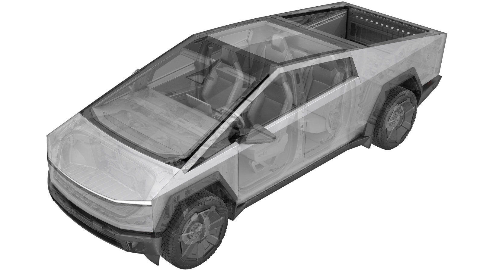 Correction code
31002300
FRT
1.20
NOTE: Unless
otherwise explicitly stated in the procedure, the correction code and its
associated FRT reflect all of the work required to perform this procedure,
including the linked procedures. Do not stack correction
codes unless explicitly told to do so.
NOTE: See Flat Rate Times to
learn more about FRTs and how they are created.
NOTE: See Personal Protection to make
sure you are wearing proper PPE when performing the procedure below.
NOTE: See Ergonomic Precautions for safe and healthy
working practices.
Correction code
31002300
FRT
1.20
NOTE: Unless
otherwise explicitly stated in the procedure, the correction code and its
associated FRT reflect all of the work required to perform this procedure,
including the linked procedures. Do not stack correction
codes unless explicitly told to do so.
NOTE: See Flat Rate Times to
learn more about FRTs and how they are created.
NOTE: See Personal Protection to make
sure you are wearing proper PPE when performing the procedure below.
NOTE: See Ergonomic Precautions for safe and healthy
working practices.
- 2025-10-23: Removed obsoleted step to run stop hold routine.
- 2024-12-09: Removed instruction to add the test drive correction code. The test drive is now included in the alignment FRT.
- 2024-10-14: Added note with link to alignment information video.
- 2024-07-19: Added step to run Center and Hold routine. Rearranged steps.
- 2024-06-11: Removed step to check for symmetry and added steps to calibrate front rack.
- 2024-04-18: Added link to perform Handwheel calibration that includes video.
- 2024-03-26: Updated ride height measurement underbody reference points.
-
Verify turn plates and slip plates are locked.
NoteAlignment machine may vary per Service Center.
- Open the LH front door and lower the LH front window.
-
Drive the vehicle onto the alignment rack.
NoteRecommend assistance to guide vehicle evenly onto lift. Park vehicle before turn plates.
-
On the vehicle touchscreen, navigate to , to set the ride height to medium.
-
Set tire pressures to specification.
NoteRefer to "Tire and Loading Information" label located on the driver side B-pillar - CT is 50 Psi If label is not present, reference Service Manual.
- Connect a laptop with Toolbox 3 to the vehicle. See Toolbox 3 (Connect and Disconnect).
- Unlock the vehicle Gateway. See Gateway (Unlock).
-
Clear Straight Ahead Offset.
NoteVehicle must be in Service Mode Plus to access panel. Via UI > Vehicle emblem > Chassis > Alignment & Tires > Clear Straight Ahead Offset. Via Toolbox 3 > Run: PROC_PEPS_CLEAR-STEERING-OFFSETvia Service Mode Plus:Chassis ➜ Alignment & Tires ➜ Clear Straight Ahead Offsetvia Toolbox:(link).
- Perform Handwheel calibration. See Set Handwheel Zero.
-
Verify chassis measurement tool is set to 51mm.
NoteAdjust as needed, Specification for "Zero" is 51mm.
-
Raise 4-post lift to comfortable working height.
NoteVerify rack is lowered onto locks evenly.
-
Perform ride height measurement reading at 4 designated points.
NoteVia TBX3 > >Actions >PROC_TAS_X_CALIBRATE-RIDE-HEIGHTvia Toolbox:(link)Verify results do not deviate more than +/- 5mm, Check specifications in Service Manual, Rear height specifications differ depending on size of rear tires.
-
Latch seat belt to driver buckle.
-
Manually latch LH front door.
NoteUse pocket screw driver to manually latch door.
-
Place vehicle in neutral.
NoteEnter vehicle > Enable Jack Mode > Shift to neutral > Close driver's door latch, Ensure climate control and exterior lighting is turned off.
-
Position vehicle evenly onto turn plates.
NoteVerify turn plates are centered to front wheels. Recommend assistance if needed, Slowly roll vehicle evenly onto turn plates.
-
Place wheel chocks on both sides of LH rear wheel.
-
Install alignment heads onto all four wheels.
NotePosition alignment heads centered to wheel, Adjust side arms as necessary to grip tires securely.
-
Perform rolling compensation.
NoteMove vehicle using LH rear wheel, Use chocks to prevent vehicle from rolling away, Reinstall the chalks to secure vehicle after rolling compensation is done.
-
Apply brake pedal depressor.
-
On the vehicle touchscreen, navigate to to disable the rear steer actuator.
NoteIf using Toolbox 3, click Actions, and then run PROC_RSA_RAMP-TO-ZEROvia Service Mode Plus:Chassis ➜ Alignment & Tires ➜ Center+Hold Rearvia Toolbox:(link).NoteThis will move the rear rack to the center and disable it.
-
Perform caster sweep.
NoteSee instructions indicated via alignment machine display.
-
Use exterior door handle to release LH front door latch.
-
Unlatch LH front seat belt.
-
On the vehicle touchscreen, navigate to
NoteFront rack will move to center and hold until timeout value reached. Adjust timeout value as required.
-
Verify vehicle alignment is within specification.
NotePrint before/after results alignment summary. If vehicle is out of specification perform adjustment accordingly.
-
Perform rear toe adjustment.
Note2x jam nuts per side, 27mm & 32mm, 70 Nm, Loosen outboard jam nut, then inboard, Adjust 22mm turn buckle as necessary, Tighten inboard, then outboard once adjustment is done.
-
Perform front toe adjustment.
Note1x rod, 15mm, 1x nut, 24mm, 90 Nm, Loosen the jam nuts and turn the inner turnbuckle CW or CCW in the direction indicated by the alignment equipment to achieve the in-spec “green” value, Tighten inboard then outboard once adjustment is done.
-
Verify vehicle alignment is within specification.
NotePrint before/after results alignment summary. If vehicle is out of specification perform adjustment accordingly.
-
Remove alignment heads from all four wheels.
-
Lower 4-post lift fully.
-
Remove wheel chocks from LH rear wheel.
-
Remove brake pedal depressor.
- Raise the LH front window and close the LH front door.
- Remove vehicle from 4-post lift.
-
Perform test drive.
NoteDrive at a minimum speed of 40 kph (25 mph) in a straight line and check for excessive pull. Verify that the steering wheel is centered when the vehicle is driving straight.