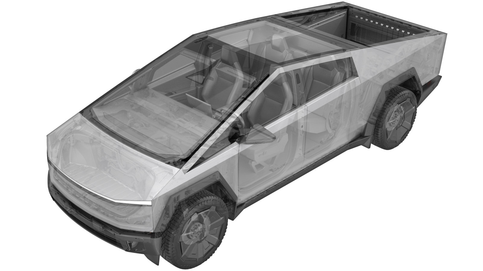
Tie Rod - Inner - Front Steering Gear - LH (Remove and Replace)
 Correction code
3201010071, 3201010072
0.54
NOTE: Unless otherwise explicitly stated in the procedure, the above correction code and FRT reflect all of the work required to perform this procedure, including the linked procedures. Do not stack correction codes unless explicitly told to do so.
NOTE: See Flat Rate Times to learn more about FRTs and how they are created. To provide feedback on FRT values, email ServiceManualFeedback@tesla.com.
NOTE: See Personal Protection to make sure wearing proper PPE when performing the below procedure.
NOTE: See Ergonomic Precautions for safe and healthy working practices.
- Raise and support the vehicle. See Raise Vehicle - 2 Post Lift.
- Open the LH front door and lower the LH front window.
-
Remove the LH front wheel. See Wheel Assembly (Remove and Install).
NoteRemove the mid aeroshield while the vehicle is lifted before lowering to remove the wheel.
- Remove the mid aeroshield. See Skid Plate - Rear (Remove and Install)
-
Loosen LH outer tie rod end jam nut
Note1x nut, 24mm, 90 Nm
-
Remove nut securing LH tie rod end to knuckle
Note1x nut, 21mm, 170 Nm
-
Remove LH tie rod end from knuckle
-
Remove LH outer tie rod end from front steering rack assembly
NoteCount how many turns it takes to fully remove and write this down you will need it when installing the tie rod end again
-
Remove bellows seal clip from bellows
Note1x clip
-
Remove large bellows clamp from bellows
Note1x clamp
-
Slide bellows toward LH outer tie rod end
NoteYou need to access the LH inner tie rod end inner ball joint
-
Remove LH inner tie rod end from pinion housing
Note1x inner tie rod, 38 crowfoot, 105 Nm, Twist until it comes off
-
Install LH inner tie rod onto pinion housing
Note1x inner tie rod, 38 crowfoot, 105 Nm, Twist until it's fully seated
-
Torque LH inner tie rod onto pinion housing
Note1x inner tie rod, 38 crowfoot, 105 Nm
-
Slide bellows into clamping position
NoteSlide bellows over pinion housing in preparation for clamping
-
Secure large bellows clamp onto bellows
Note1x clamp
-
Secure bellows seal clip onto bellows
Note1x clip
-
Install LH outer tie rod end onto front steering rack assembly
NoteTurn the outer tie rod end exactly the amount of rotations it took to remove it, This ensures the alignment is as close as possible to where it was originally
-
Position LH tie rod end onto knuckle
-
Install nut securing LH tie rod end to knuckle
Note1x nut, 21mm, 170 Nm
-
Secure tie rod end jam nut
Note1x nut, 24mm, 90 Nm
- Raise and support the vehicle. See Raise Vehicle - 2 Post Lift.
- Open the LH front door and lower the LH front window.
-
Install the LH front wheel. See Wheel Assembly (Remove and Install).
NoteInstall the mid aeroshield before lowering the vehicle.
- Install the mid aeroshield. See Skid Plate - Rear (Remove and Install)
- Remove the vehicle from the lift. See Raise Vehicle - 2 Post Lift.
- Raise the LH front window and close the LH front door.
-
Perform test drive
NotePerform a validation test drive after repair Drive a minimum speed of 25mph, Drive in a straight line and check for excessive pull, Verify the steering wheel is centered when vehicle is driving straight, Determine whether an alignment is recommended Add correction code 00040100 as needed