Ancillary Cover (Remove and Install)
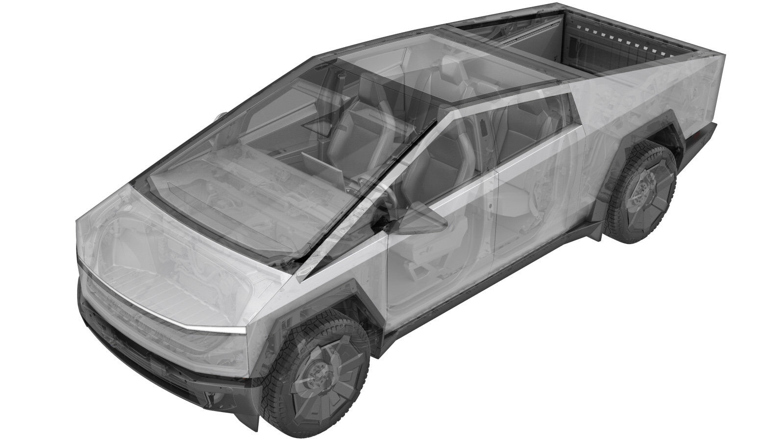 Correction code
1630010101
1630010102
FRT
3.18
NOTE: Unless
otherwise explicitly stated in the procedure, the correction code and its
associated FRT reflect all of the work required to perform this procedure,
including the linked procedures. Do not stack correction
codes unless explicitly told to do so.
NOTE: See Flat Rate Times to
learn more about FRTs and how they are created.
NOTE: See Personal Protection to make
sure you are wearing proper PPE when performing the procedure below.
NOTE: See Ergonomic Precautions for safe and healthy
working practices.
Correction code
1630010101
1630010102
FRT
3.18
NOTE: Unless
otherwise explicitly stated in the procedure, the correction code and its
associated FRT reflect all of the work required to perform this procedure,
including the linked procedures. Do not stack correction
codes unless explicitly told to do so.
NOTE: See Flat Rate Times to
learn more about FRTs and how they are created.
NOTE: See Personal Protection to make
sure you are wearing proper PPE when performing the procedure below.
NOTE: See Ergonomic Precautions for safe and healthy
working practices.
- 2025-11-10: VOSS fittings are reusable. Removed steps that instructed to discard fitting.
- 2024-11-22: Added warning to NOT skip steps to remove the tonneau slats.
- 2024-04-10: Added step to install Ancillary Access Bench (2035746-00-A)
High Voltage Awareness Care Pointsfor additional glove and safety information.
Remove
- Raise and support the vehicle. See Raise Vehicle - 2 Post Lift.
- Remove the tonneau slats. See Slat System - Tonneau (Remove and Install).
- Remove the rear underhood apron. See Underhood Apron - Rear (Remove and Install).
- Disconnect MV power. See Mid-Voltage Power (Disconnect and Connect) (Modify).
- Perform Vehicle HV Disablement procedure. See Vehicle HV Disablement Procedure (without Terrestrial Armor) (Test/Adjust).
-
Disconnect the pressurized pack
lines.
Note12 mm, 8 Nm
-
Secure the RDU header connector to the
ancillary.
Notex1 connectorNoteVerify the lever is in the upright and open position. Carefully seat connector and allow the lever to engage. Fully secure the lever and verify that the red tab is locked.CAUTIONDo not damage any pins.
- Remove the pyro access cover. See Cover - Pyro Access - HV Battery (Remove and Install).
- Remove the primary and secondary pyro fuses. See Pyro Disconnect (Remove and Install).
- Remove the leather over gloves and HV insulating gloves.
- Lower the vehicle until the tires are touching the ground.
- Remove the bed floor assembly. See Bed Floor Assembly (Remove and Install).
-
Remove the bolts (x6) that attach the
RH tonneau NVH cover.
 5 Nm (3.7 lbs-ft)TipUse of the following tool(s) is recommended:
- 10 mm socket
Note2-peice NVH assembly order of operations requires RH side to be released first to allow busbar clearance for LH side removal. -
Remove the RH tonneau NVH cover.
NoteRelease rearward, and then slide over the LH side NVH cover before removing upward.
-
Remove the bolts (x5) that attach the
LH tonneau NVH cover.5 Nm (3.7 lbs-ft)TipUse of the following tool(s) is recommended:
- 10 mm socket
-
Remove the LH tonneau NVH cover.
NoteSlide towards the center. Ensure busbar clearance during removal to avoid damage to the NVH material.
-
Remove the screws (x8) that attach the
tonneau coverbox cross supports.5 Nm (3.7 lbs-ft)TipUse of the following tool(s) is recommended:
- Torx T25 socket
-
Clean all debris from the ancillary
cover.
NoteDuring the removal of the ancillary cover, any debris on top of the cover may be deposited into the ancillary bay.
-
Release the pressurize pack air line
from the ancillary.
Notex1 connectorCAUTIONDo not release air line to the reservoir. Rapid loss of pressure will result if the wrong air line is released.
-
Disconnect the electrical connector,
and then remove the bolt that attaches the pressurize pack valve block to the air
suspension reservoir.5 Nm (3.7 lbs-ft)TipUse of the following tool(s) is recommended:
- 10 mm socket
Notex1 clip, x1 zip tieNoteRelease the lock before disengaging the connector.NoteCut the zip tie at the reservoir/ancillary air line bundle.NoteRelease the harness clip at the bracket. -
Release the air suspension valve
block.
Notex3 rubber grommetsNoteRotate clockwise until the top 2 rubber feet have released from the bracket. Pull upwards at a 45 degree angle to release the bottom rubber foot from the bracket.NoteLeave all air lines and connections secured, and then set the assembly aside.
-
Remove the nuts (x2) that attach the
air suspension reservoir to the body.33 Nm (24.3 lbs-ft)TipUse of the following tool(s) is recommended:
- 13 mm socket
Notex2 fir tree clips -
Put the air suspension reservoir in
service position, and then install the Ancillary Access Bench (2035746-00-A).
NoteRaise and swing the air suspension reservoir to the side of the bed.
-
Disconnect the ancillary bay MV
electrical connector.
NoteDouble locking: Release the tab, and then pivot the lever. Release the second tab to disengage the electrical connector. Wait 1 second between locking tab release to discharge and prevent arcing.
-
Remove the bolt that attaches the
busbar HV connector lid.9 Nm (6.6 lbs-ft)TipUse of the following tool(s) is recommended:
- 10 mm socket
-
Remove the bolts (x2) that attach the
HV connector to the DC FC header.9 Nm (6.6 lbs-ft)TipUse of the following tool(s) is recommended:
- 10 mm socket
-
Release the HV connector from the DC FC header, and then use an inflatable airbag to suspend the busbar assembly above the ancillary assembly.
NoteUpon separation, check for grease around the inner perimeter of the DC FC header. If present, additional steps will need to be performed later.
-
Support the HV busbar assembly to
maintain clearance with a bungee cord.
-
Remove the bolts (x2) that attach the
fast charger header doubler.10 Nm (7.4 lbs-ft)TipUse of the following tool(s) is recommended:
- External Torx E10 5-Lobe
-
Remove the bolts (x2) that attach the
low voltage header.6 Nm (4.4 lbs-ft)TipUse of the following tool(s) is recommended:
- 10 mm socket
-
Remove the bolts (x22) that attach the
ancillary cover to the HV battery.6 Nm (4.4 lbs-ft)TipUse of the following tool(s) is recommended:
- External Torx E10 5-Lobe
NoteUse E10 5-Lobe socket without magnet.NoteThe bolts are captive and will stay attached to the ancillary cover. Follow fastening order. -
Remove the ancillary cover.
NoteUse a suction cup and maneuver around the busbar and the tonneau cage.
-
If grease was found around the inner perimeter of the DC FC header, use a disposable towel to wipe the grease off the header and the busbar connector.
NoteDo not allow the grease to contact the busbar HV mating surfaces.
Install
-
Install the ancillary cover.
NoteUse a suction cup.NoteManeuver around the busbar and tonneau cage.
-
Install the bolts (x22) that attach
the ancillary cover to the HV battery.6 Nm (4.4 lbs-ft)TipUse of the following tool(s) is recommended:
- External Torx E10 5-Lobe
NoteUse E10 5-Lobe socket without magnet.NoteThe bolts are captive and will stay attached to the ancillary cover. Follow fastening order. -
Install the bolts (x2) that attach the
low voltage header.6 Nm (4.4 lbs-ft)TipUse of the following tool(s) is recommended:
- 10 mm socket
-
Install the bolts (x2) that attach the
fast charger header doubler.10 Nm (7.4 lbs-ft)TipUse of the following tool(s) is recommended:
- External Torx E10 5-Lobe
-
If grease was found inside the DC FC header, prepare the grease gun with Mobil XTCE grease, apply a 6 mm diameter continuous bead around the DC FC header inner perimeter, and then use a gloved finger wetted with alcohol to smear the grease up the inner wall to a height of 10 mm.
NoteThe grease is part number 1089958-00-A and is available from eProcurement.
-
Clean the HV connector contact surface
of residual Penetrox with IPA wipe.
NoteAllow 1 minute dry time after removing Penetrox.
-
Clean the busbar HV connector contact
surface of residual Penetrox with an Isopropyl Alcohol (IPA) wipe.
NoteAllow 1 minute dry time after removing Penetrox.NoteIt is necessary to clean the HV connector during re-use of the busbar.
-
Apply Penetrox onto the HV connector
joints.
NoteApply 2 drops of Penetrox A-13 about 5 mm in diameter to either side of the hole on both leads. Spread evenly to verify the contact surface is fully covered.
-
Position the busbar connector, and
then lower it onto the HV header.
NoteRemove the bungee cord.
-
Install the bolts (x2) that attach the
charge port busbar kit to the HV header.9 Nm (6.6 lbs-ft)TipUse of the following tool(s) is recommended:
- 10 mm socket (insulated)
-
Inspect the HV insulating
gloves.
NoteCheck the gloves for damage prior to use. Refer to service document TN-15-92-003 for information on inspecting HV gloves.
-
Put on the HV insulating gloves and
leather over gloves.
-
Perform a Hioki resistance test at
each HV joint from the HV busbar lead to the bolt head.
Notex2 HV jointsNoteWhen using a Hioki tester, verify the meter has been properly adjusted and set prior to usage.NoteThe acceptable resistance is between 0.050 mΩ (50 μΩ) and 0.195 mΩ (195 μΩ).
- If the resistance is greater than 0.195 mΩ (195 μΩ), there is too much resistance in the High Voltage joint. Remove the fastener, clean areas with isopropyl alcohol, install fastener back and test again.
- If the resistance is lower than 0.050 mΩ (50 μΩ), reposition the probes and measure again.
- If the resistance is repeatedly between 0.00 mΩ and 0.050 mΩ (50 μΩ), the Hioki test passed. proceed to the next step.
- Remove the leather over gloves and HV insulating gloves.
-
Install the bolt that attaches the
busbar HV connector lid.9 Nm (6.6 lbs-ft)TipUse of the following tool(s) is recommended:
- 10 mm socket
-
Connect the ancillary bay MV
electrical connector.
NoteDouble locking: Rotate the lever into the second lock. Perform a pull test to ensure the electrical connector is engaged correctly.
-
Install the screws (x8) that attach
the tonneau coverbox cross supports.5 Nm (3.7 lbs-ft)TipUse of the following tool(s) is recommended:
- Torx T25 socket
NoteSupports install in the same direction of the fasteners. -
Install the LH tonneau NVH
cover.
NoteMake sure the busbar clearance during installation to avoid damage to the NVH material.
-
Install the bolts (x5) that attach the
LH tonneau NVH cover.5 Nm (3.7 lbs-ft)TipUse of the following tool(s) is recommended:
- 10 mm socket
-
Install the RH tonneau NVH
cover.
-
Install the bolts (x6) that attach the
RH tonneau NVH cover.5 Nm (3.7 lbs-ft)TipUse of the following tool(s) is recommended:
- 10 mm socket
-
Remove the Ancillary Access Bench, and
then put the air suspension reservoir into position for installation.
-
Install the nuts (x2) that attach the
air suspension reservoir.33 Nm (24.3 lbs-ft)TipUse of the following tool(s) is recommended:
- 13 mm socket
Notex2 fir tree clips -
Secure the air suspension valve
block.
Notex3 rubber grommetsNoteRotate counterclockwise until the top 2 rubber feet are secured onto the bracket. Push downwards at a 45 degree angle to secure the bottom rubber foot into bracket.NotePosition air lines and connections into place for installation.
-
Secure the pressurize pack air line
from the ancillary to the valve block.
Notex1 lineNoteRemove the plastic cap from the VOSS fittings. Press the air lines into the fitting until the mark aligns with the top of the fitting. Verify the line is properly secured by performing a push-pull test.
-
Install the bolt that attaches the
pressurize pack valve block to the air suspension reservoir, and then connect the
electrical connector.5 Nm (3.7 lbs-ft)TipUse of the following tool(s) is recommended:
- 10 mm socket
Notex1 clip, x1 zip tieNoteSecure the reservoir and ancillary air lines at the white marked sections. - Install the bed floor assembly. See Bed Floor Assembly (Remove and Install).
- Fully raise the vehicle.
-
Inspect the HV insulating
gloves.
NoteCheck gloves for damage prior to use. Refer to service document TN-15-92-003 for information on inspecting the HV gloves.
-
Put on the HV insulating gloves and
leather over gloves.
-
Clean the mating surface of the
pyro.
NoteUse a non-conductive plastic tool to clean the busbar side. Allow 1 minute for the Isopropyl Alcohol (IPA) to fully dry.CAUTIONDo not use any other types of cleaner.
- Install the primary and secondary pyro fuses. See Pyro Disconnect (Remove and Install).
- Remove the leather over gloves and HV insulating gloves.
-
Install the bolts (x4) that attach the
pyro fuse access cover.10 Nm (7.4 lbs-ft)TipUse of the following tool(s) is recommended:
- External Torx E10 5-Lobe
NoteMake sure that the seal is fully seated and undamaged. -
Install the pressurized pack lines
(x2).8 Nm (5.9 lbs-ft)TipUse of the following tool(s) is recommended:
- 12 mm 6 point flare nut wrench
- 12 mm flare nut crowfoot socket
NoteRemove the plastic caps from the VOSS fittings. Press the air lines into the fitting until the mark aligns with the top of the fitting. Verify the line is properly secured by performing a push-pull test. -
Install the mid aero shield.
Notex6 clips; x3 bolts, 15 mm, 42 Nm; x5 bolts, 13 mm, 28 Nm; x2 bolts, 10 mm, 6 NmNoteApply Loctite 222 onto mid aero shield bolts and install the fasteners.
- Fully lower the vehicle.
- Connect MV power. See Mid-Voltage Power (Disconnect and Connect) (Modify).
- Install the rear underhood apron. See Underhood Apron - Rear (Remove and Install).
- Close the powered frunk.
- Install the tonneau slats. See Slat System - Tonneau (Remove and Install).
- Remove the vehicle from the lift. See Raise Vehicle - 2 Post Lift.