Drive Unit - Front (Remove and Replace)
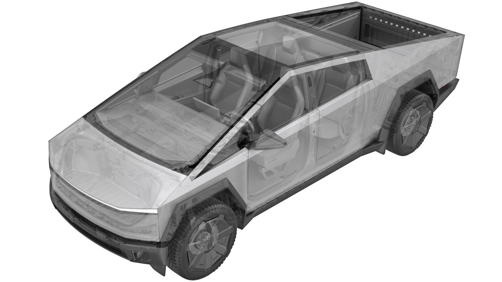 Correction code
3901049112
FRT
3.66
NOTE: Unless
otherwise explicitly stated in the procedure, the correction code and its
associated FRT reflect all of the work required to perform this procedure,
including the linked procedures. Do not stack correction
codes unless explicitly told to do so.
NOTE: See Flat Rate Times to
learn more about FRTs and how they are created.
NOTE: See Personal Protection to make
sure you are wearing proper PPE when performing the procedure below.
NOTE: See Ergonomic Precautions for safe and healthy
working practices.
Correction code
3901049112
FRT
3.66
NOTE: Unless
otherwise explicitly stated in the procedure, the correction code and its
associated FRT reflect all of the work required to perform this procedure,
including the linked procedures. Do not stack correction
codes unless explicitly told to do so.
NOTE: See Flat Rate Times to
learn more about FRTs and how they are created.
NOTE: See Personal Protection to make
sure you are wearing proper PPE when performing the procedure below.
NOTE: See Ergonomic Precautions for safe and healthy
working practices.
- 2026-05-01: Added tool list.
- 2024-07-29: Updated Toolbox routine.
Equipment:
- 1498673-00-A KIT, CABLE AXLE REMOVER, MS/MX/M3
- 1130279-00-A Lifting Sling, Drive Unit, Model 3 (NA, APAC)
- 1099645-99-D FIXTURE, SUBFRAME, MODEL 3/Y CYBERTRUCK
- 1066521-00-A Powertrain Table
- 1081765-00-A 3/4 TON UNDERHOIST STAND
High Voltage Awareness Care Pointsfor additional glove and safety information.
Remove
- Remove the front drive unit assembly. See Drive Unit - Front (Remove and Install).
Install
- Install the front drive unit assembly. See Drive Unit - Front (Remove and Install).
- Connect a laptop with Toolbox 3 to the vehicle. See Toolbox 3 (Connect and Disconnect).
- In Toolbox, click the Dashboards tab, and then search for "Drive Unit".
- Click PROC_PMF_X_WRITE-DRIVE-TYPEvia Service Mode Plus:Drive Unit ➜ Front Drive Unit Replacement ➜ Write Drive Typevia Toolbox:(link), click Run, and allow the routine to complete.
-
On the vehicle touchscreen, navigate
to Service Mode UI > Software Reinstall
> Reinstall to reinstall the vehicle software.
NoteThe installation will begin immediately.
- Re-establish vehicle connection to Toolbox 3.
- In Toolbox, click the Dashboards tab, and then search for "Drive Unit".
-
Click PROC_DI_X_PAIR-IMMOBILIZER-AND-VEHICLE-ODOMETERvia Service Mode Plus:
- Drive Inverter ➜ Rear Drive Inverter Replacement ➜ Immobilizer/ODO Pairing
- Drive Unit ➜ Rear Drive Unit Replacement ➜ Pair Immobilizer and Vehicle Odometer
- Disconnect Toolbox and remove the laptop from the vehicle. See Toolbox 3 (Connect and Disconnect).
- Exit Service mode. See Service Mode.
- Remove the vehicle from the lift. See Raise Vehicle - 2 Post Lift.
- Raise the LH front window and close the LH front door.
- Review wheel alignment requirements and add correction code as needed.