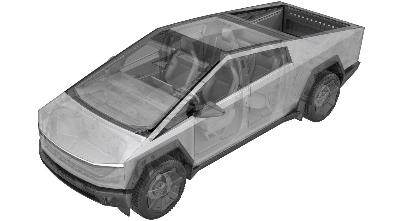
AC Junction Box (Remove and Install)
 Correction code
1630010221
1630010222
FRT
3.42
NOTE: Unless
otherwise explicitly stated in the procedure, the above correction code and
FRT reflect all of the work required to perform this procedure, including
the linked procedures. Do
not stack correction codes unless explicitly told to do so.
NOTE: See Flat Rate Times to learn more about FRTs and how
they are created. To provide feedback on FRT values, email ServiceManualFeedback@tesla.com.
NOTE: See Personal Protection
to make sure wearing proper PPE when performing the below procedure.
NOTE: See Ergonomic Precautions for safe and
healthy working practices.
- 2024-11-22: Added warning to NOT skip steps to remove the tonneau slats.
- 2024-04-10: Added step to install Ancillary Access Bench (2035746-00-A)
Remove
- Raise and support the vehicle. See Raise Vehicle - 2 Post Lift.
- Remove the tonneau slats. See Slat System - Tonneau (Remove and Install).
- Unlock the vehicle Gateway. See Gateway (Unlock).
- Remove the ancillary cover. See Ancillary Cover (Remove and Install).
-
Release the connector locks, and then
disconnect the ACJB to PCS HV jumper harness electrical connectors (x2).
CAUTIONOnly pull from the connector housing when disconnecting the connector. Do not pull on the harness wires.
-
Release the connector locks, and then
disconnect the ACJB LV connector and ACJB to device cluster HV connectors (x2).
NotePress the levers to release the clips, and then pull the connector housing to disconnect the connector.CAUTIONOnly pull from the connector housing when disconnecting the connector. Do not pull on the harness wires.
-
Release the connector locks, and then
disconnect the ancillary connectors to center console outlet and bed outlet electrical
connectors.
NoteSlide the locks to release the connector.
-
Remove the bolt that attaches the ACJB
header to the vehicle.
TIpUse of the following tool(s) is recommended:
- Torx T25 socket
-
Remove the bolts (x6) that attach the
ACJB assembly to the vehicle.
 6 Nm (4.4 lbs-ft)TIpUse of the following tool(s) is recommended:
- E10 5 Lobe Torx
-
Release the clips (x2) that attach the
ACJB to the ancillary tray.
NoteRelease clips at headers, and then slide the ACJB inboard on the datums.
-
Remove the ACJB from the ancillary
tray.
NoteLift the ACJB over and out of the PCS once headers clear outboard side of ancillary tray.
Install
-
If grease was found around the inner perimeter of the DC FC header, use a disposable towel to wipe the grease off the header and the busbar connector.
NoteDo not allow the grease to contact the busbar HV mating surfaces.
-
Install the ACJB into the ancillary
tray.
NoteAlign the header, and then slide the openings to the datums in the ancillary tray.
-
Slide the ACJB into the ancillary tray
until the header clips are fully engaged.
NoteMake sure all fastener holes are aligned.
-
Install the bolts (x6) that attach the ACJB assembly to the vehicle.
 6 Nm (4.4 lbs-ft)TIpUse of the following tool(s) is recommended:
- E10 5 Lobe Torx
-
Install the bolt that attaches the ACJB header to the vehicle.
TIpUse of the following tool(s) is recommended:
- Torx T25 socket
-
Connect the ancillary connectors to center console outlet and bed outlet electrical,
and then secure the connector locks.
-
Position the ACJB to PCS HV jumper
harness into the vehicle, and then connect the electrical connectors (x2) and secure the
connector locks.
NoteSecure at the ACJB first, and then fold the harness over to the PCS
-
Connect the ACJB LV harness connector
and ACJB HV harness to the device cluster connector, and then secure the connector
locks.
- Install the ancillary cover. See Ancillary Cover (Remove and Install).
- On the vehicle touchscreen, navigate to to reinstall the vehicle software.
- Exit Service Mode. See Service Mode.
- Remove the vehicle from the lift. See Raise Vehicle - 2 Post Lift.