2026-02-05

Control Arm - Lower - Front - LH (Remove and Install)
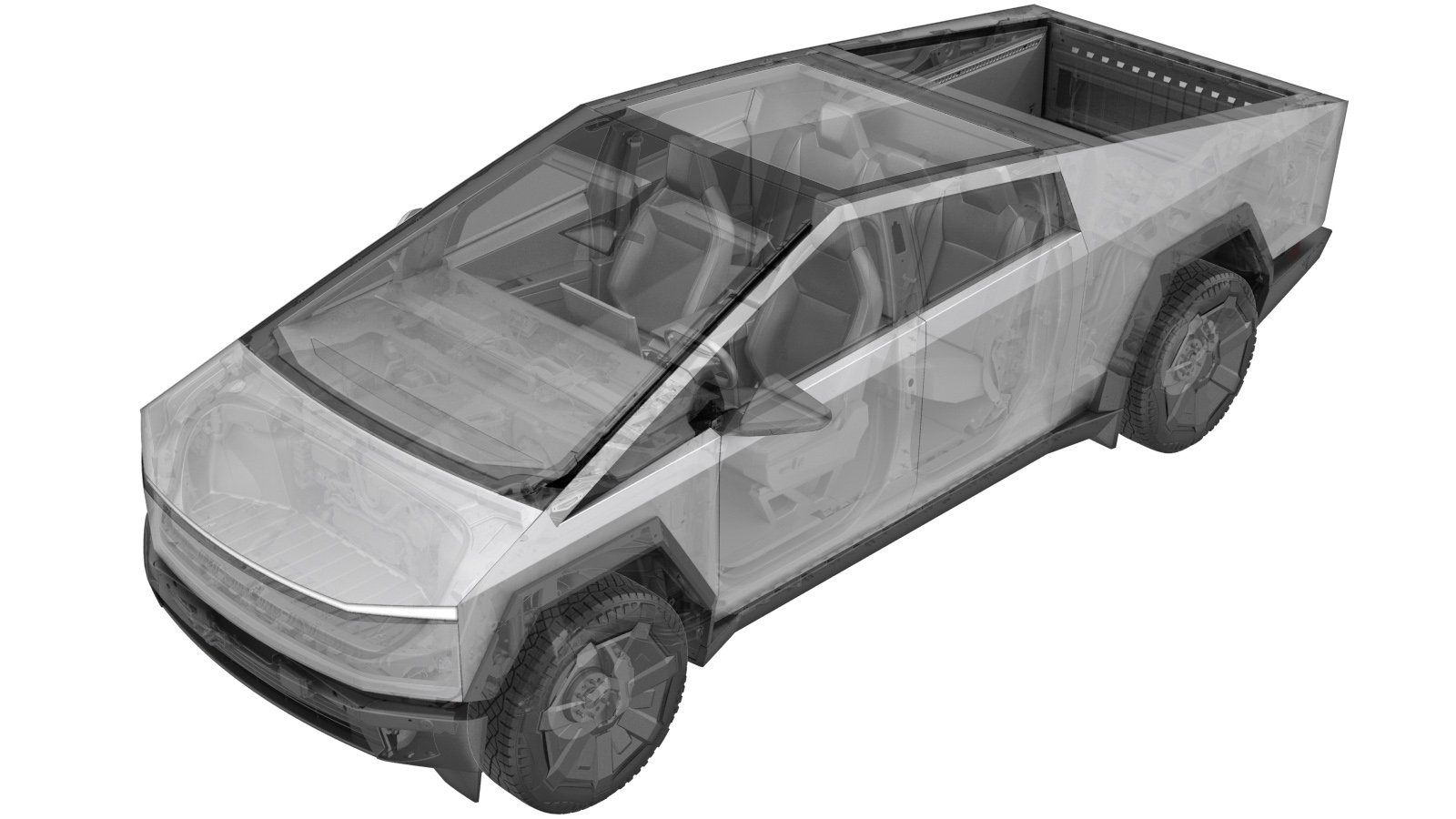
Correction code 3101065031 3101065032 3101065041 3101065042 0.54 NOTE: Unless otherwise explicitly stated in the procedure, the correction code and FRT listed above reflect all of the work required to perform this procedure, including the linked procedures. Do not stack correction codes unless explicitly told to do so. NOTE: See Flat Rate Times to learn more about FRTs and how they are created. NOTE: See Personal Protection to make sure you are wearing proper PPE when performing the procedure below. NOTE: See Ergonomic Precautions for safe and healthy working practices.

  • 2026-02-05: Updated to latest time study.
Table 1. Torque Specifications: Front Suspension
Description Torque Value Recommended Tools Reuse/Replace Notes
Smaller bolts (x2) that attach the LH front lower control arm to the subframe
175 Nm (129.1 lbs-ft)
  • 21 mm socket
Replace
Bolts (x2) that attach the LH front air spring module to the LH front lower control arm
140 Nm (103.2 lbs-ft)
  • 21 mm socket
Reuse
Larger bolt that attaches the LH front lower control arm to the subframe
300 Nm (221.2 lbs-ft)
  • 24 mm socket
Replace
Nut that attaches the LH front lower control arm to the LH front knuckle
190 Nm (140.1 lbs-ft)
  • 24 mm socket
Reuse
Nut that attaches the LH front stabilizer bar end link to the LH front lower control arm
275 Nm (202.8 lbs-ft)
  • 21 mm socket
Replace
Warning IconA warning icon, calling your attention to a possibly risky situation
Warning
This procedure is a DRAFT. Although it has been validated, Warnings and Cautions might be missing. Follow safety requirements and use extreme caution when working on or near High Voltage systems and components.

Remove

  1. Open the LH front door and lower the LH front window.
  2. Raise and support the vehicle. See Raise Vehicle - 2 Post Lift.
  3. Connect a laptop with Toolbox 3 to the vehicle. See Toolbox 3 (Connect and Disconnect).
  4. In Toolbox, click the Actions tab, and then search for "TAS service run".
  5. Click the TAS Enter Service Run Mode, and then click Run. Allow the routine to complete.
    Informational PurposesAn informational icon, calling your attention
    Note
    Click the X at the top right of window to close once complete.
  6. Click the Actions tab, and then search for "TAS deflate".
  7. Click the TAS Deflate Component, and then click Run. Allow the routine to complete.
    Informational PurposesAn informational icon, calling your attention
    Note
    Select "FL" from the drop-down menu. Click the X at the top right of window to close once complete.
  8. Remove the LH front wheel cover. See Wheel Cover - Front - LH (Remove and Install).
  9. Loosen the wheel lug nuts (x6).
    205 Nm (151.2 lbs-ft)
    .
    Informational PurposesAn informational icon, calling your attention
    TIp
    Use of the following tool(s) is recommended:
    • 21 mm deep socket
  10. Loosen the LH front halfshaft bolt.
    Informational PurposesAn informational icon, calling your attention
    TIp
    Use of the following tool(s) is recommended:
    • 24 mm socket
  11. Remove the LH front wheel. See Wheel Assembly (Remove and Install).
  12. Remove and discard the LH front halfshaft bolt.
    Informational PurposesAn informational icon, calling your attention
    TIp
    Use of the following tool(s) is recommended:
    • 24 mm socket
  13. Remove the bolt that attaches the LH front brake hose bracket to the knuckle.
    10 Nm (7.4 lbs-ft)
    Informational PurposesAn informational icon, calling your attention
    TIp
    Use of the following tool(s) is recommended:
    • 10 mm deep socket
  14. Remove the bolts (x2) that attach the LH front caliper to the knuckle, and then set the caliper aside with an S-hook.
    Informational PurposesAn informational icon, calling your attention
    TIp
    Use of the following tool(s) is recommended:
    • 24 mm socket
    Informational PurposesAn informational icon, calling your attention
    Note
    The rotor will be loose until the caliper is installed. Use a lug nut to secure the rotor to the hub.
  15. Remove front aero shield. See Aeroshield - Front (Remove and Install).
  16. Remove the bolts (x3) that attach the LH lower control arm shield to the vehicle, and then remove the shield from the vehicle.
    7 Nm (5.2 lbs-ft)
    Informational PurposesAn informational icon, calling your attention
    TIp
    Use of the following tool(s) is recommended:
    • 10 mm socket
  17. Remove the bolts (x2) that attach the LH front air spring module to the lower control arm.
    140 Nm (103.2 lbs-ft)
    Warning IconA warning icon, calling your attention to a possibly risky situation
    Warning
    Be prepared for some spring load to release from the bushings.
    Informational PurposesAn informational icon, calling your attention
    TIp
    Use of the following tool(s) is recommended:
    • 21 mm socket
  18. Remove the nut that attaches the LH tie rod end to the knuckle.
    Informational PurposesAn informational icon, calling your attention
    TIp
    Use of the following tool(s) is recommended:
    • 21 mm socket
  19. Remove the nut that attaches the LH front upper control arm to the knuckle.
    Informational PurposesAn informational icon, calling your attention
    TIp
    Use of the following tool(s) is recommended:
    • 18 mm socket
    Informational PurposesAn informational icon, calling your attention
    Note
    Use a step ladder as needed.
  20. Remove and discard the nut that attaches the LH front end link to the lower arm, and then remove the end link from the lower control arm.
    275 Nm (202.8 lbs-ft)
    Informational PurposesAn informational icon, calling your attention
    Note
    Counter hold the stud while removing the nut.
    Informational PurposesAn informational icon, calling your attention
    TIp
    Use of the following tool(s) is recommended:
    • 21 mm socket
  21. Remove and discard the nut that attaches the LH front lower arm to the knuckle, and then remove the lower control arm from the knuckle.
    190 Nm (140.1 lbs-ft)
    Informational PurposesAn informational icon, calling your attention
    TIp
    Use of the following tool(s) is recommended:
    • 24 mm socket
  22. Remove and discard the smaller bolts (x2) that attach the LH front lower control arm to the subframe.
    175 Nm (129.1 lbs-ft)
    Informational PurposesAn informational icon, calling your attention
    TIp
    Use of the following tool(s) is recommended:
    • 21 mm socket
  23. Remove and discard the larger bolt that attaches the LH front lower control arm to the subframe, and then remove the lower control arm from the vehicle.
    300 Nm (221.2 lbs-ft)
    Informational PurposesAn informational icon, calling your attention
    TIp
    Use of the following tool(s) is recommended:
    • 24 mm socket

Install

  1. Position the LH front lower control arm to the subframe, and then install new smaller bolts (x2) that attach the control arm to the subframe.
    175 Nm (129.1 lbs-ft)
    Informational PurposesAn informational icon, calling your attention
    TIp
    Use of the following tool(s) is recommended:
    • 21 mm socket
  2. Install a new larger bolt that attaches the control arm to the subframe.
    300 Nm (221.2 lbs-ft)
    Informational PurposesAn informational icon, calling your attention
    TIp
    Use of the following tool(s) is recommended:
    • 24 mm socket
  3. Position the LH front knuckle to the front upper control arm, and then install nut that attaches the knuckle to the front upper control arm.
    190 Nm (140.1 lbs-ft)
    Informational PurposesAn informational icon, calling your attention
    TIp
    Use of the following tool(s) is recommended:
    • 24 mm socket
  4. Partially install the new LH front halfshaft bolt.
    Informational PurposesAn informational icon, calling your attention
    TIp
    Use of the following tool(s) is recommended:
    • 24 mm socket
    Informational PurposesAn informational icon, calling your attention
    Note
    Do not tighten the bolt at this time. The bolt will be tighten later in this procedure.
  5. Hand tighten the LH front halfshaft onto the knuckle.
    Informational PurposesAn informational icon, calling your attention
    Note
    Torque the bolt at a later step in this procedure.
    Informational PurposesAn informational icon, calling your attention
    Note
    Hold the knuckle against the halfshaft, and then rotate the hub until splines click. Engage the splines, and then hand tighten the bolt. If the splines are properly engaged, the hub will rotate the halfshaft.
  6. Install the nut that attaches the LH tie rod end to the knuckle.
    170 Nm (125.4 lbs-ft)
    Informational PurposesAn informational icon, calling your attention
    TIp
    Use of the following tool(s) is recommended:
    • 21 mm socket
    Informational PurposesAn informational icon, calling your attention
    Note
    Verify weight is evenly distributed to ease installation.
  7. Install the nut that attaches the LH front upper control arm to the knuckle.
    80 Nm (59.0 lbs-ft)
    Informational PurposesAn informational icon, calling your attention
    TIp
    Use of the following tool(s) is recommended:
    • 18 mm socket
    Informational PurposesAn informational icon, calling your attention
    Note
    Use a step stool as needed.
  8. With assistance, install the bolts (x2) that attach the LH front caliper to the knuckle.
    315 Nm (232.3 lbs-ft)
    Informational PurposesAn informational icon, calling your attention
    TIp
    Use of the following tool(s) is recommended:
    • 24 mm socket
    Informational PurposesAn informational icon, calling your attention
    Note
    The rotor will be loose until the caliper is installed.
  9. Install the bolt that attaches the LH front brake hose bracket to the knuckle.
    10 Nm (7.4 lbs-ft)
    Informational PurposesAn informational icon, calling your attention
    TIp
    Use of the following tool(s) is recommended:
    • 10 mm deep socket
  10. Position the LH front end link to the lower arm, and then install a new the nut that attaches the end link to the lower control arm.
    275 Nm (202.8 lbs-ft)
    Informational PurposesAn informational icon, calling your attention
    Note
    Counter hold the stud while installing the nut.
    Informational PurposesAn informational icon, calling your attention
    TIp
    Use of the following tool(s) is recommended:
    • 21 mm socket
  11. Install the bolts (x2) that attach the LH front air spring module to the lower control arm.
    140 Nm (103.2 lbs-ft)
    Informational PurposesAn informational icon, calling your attention
    TIp
    Use of the following tool(s) is recommended:
    • 21 mm socket
  12. Position the LH lower control arm shield to the vehicle, and then install the bolts (x3) that attach the shield to the vehicle.
    7 Nm (5.2 lbs-ft)
    Informational PurposesAn informational icon, calling your attention
    TIp
    Use of the following tool(s) is recommended:
    • 10 mm socket
  13. Install front aero shield. See Aeroshield - Front (Remove and Install).
  14. Install the LH front wheel, and then hand tighten the wheel lug nuts.
    Informational PurposesAn informational icon, calling your attention
    Note
    Tightening of the lug nuts will be performed later in this procedure.
  15. Install and hand-tighten the LH front halfshaft bolt.
    Informational PurposesAn informational icon, calling your attention
    TIp
    Use of the following tool(s) is recommended:
    • 24 mm socket
  16. Lower the vehicle until the tires are touching the ground.
    Informational PurposesAn informational icon, calling your attention
    Note
    Raise lift off locks, and then hold lock release lever to keep the locks free while the vehicle is lowered.
  17. Tighten the LH front halfshaft bolt.
    300 Nm (221.2 lbs-ft)
    Informational PurposesAn informational icon, calling your attention
    TIp
    Use of the following tool(s) is recommended:
    • 24 mm socket
  18. Tighten the wheel lug nuts (x6).
    205 Nm (151.2 lbs-ft)
    .
    Informational PurposesAn informational icon, calling your attention
    TIp
    Use of the following tool(s) is recommended:
    • 21 mm deep socket
  19. Install the LH front wheel cover. See Wheel Cover - Front - LH (Remove and Install).
  20. Connect a laptop with Toolbox 3 to the vehicle. See Toolbox 3 (Connect and Disconnect).
  21. In Toolbox, click the Actions tab, and then search for "TAS normal".
  22. Click TAS Enter Normal Run Mode, and then click Run. Allow the routine to complete.
    Informational PurposesAn informational icon, calling your attention
    Note
    Click the X at the top right of the window to close once complete.
  23. Disconnect the laptop from the vehicle. See Toolbox 3 (Connect and Disconnect).
  24. Remove the vehicle from the lift. See Raise Vehicle - 2 Post Lift.
  25. Raise the LH front window and close the LH front door.