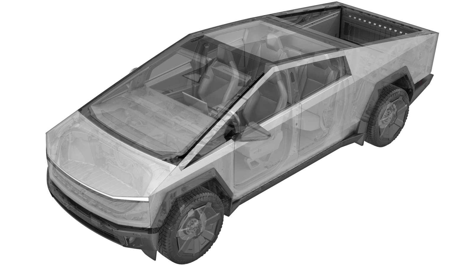
Device Cluster Assembly (Remove and Replace)
 Correction code
1630010112
FRT
3.84
NOTE: Unless
otherwise explicitly stated in the procedure, the above correction code and
FRT reflect all of the work required to perform this procedure, including
the linked procedures. Do
not stack correction codes unless explicitly told to do so.
NOTE: See Flat Rate Times to learn more about FRTs and how
they are created. To provide feedback on FRT values, email ServiceManualFeedback@tesla.com.
NOTE: See Personal Protection
to make sure wearing proper PPE when performing the below procedure.
NOTE: See Ergonomic Precautions for safe and
healthy working practices.
- 2025-10-21: Deleted steps to enter Service Mode and unlock the Gateway.
- 2024-12-05: Added note to replace the header plug with PN 1507801-20-E or later if the new device cluster has PN 1816026-XX-J or later.
- 2024-11-22: Added warning to NOT skip steps to remove the tonneau slats.
- 2024-10-11: Added replacement device cluster image with pre-installed pyro disconnects shown for clarity purposes.
- 2024-07-26: Added steps to back up and restore DCA; removed old placeholder steps.
- 2024-07-23: Added steps to check and adjust orientation of the shunts on replacement device cluster assembly before installing.
- 2024-04-09: Added check for pre-installed pyro disconnects and removal steps.
- 2024-03-27: Cleaned up topic.
Remove
-
Inspect the replacement device cluster for the presence of pre-installed pyro disconnects.
WarningDo not install a device cluster with pre-installed pyro disconnects.
- If the replacement device cluster has no pre-installed pyro disconnects, go to step 7.
- If the replacement device cluster has any pre-installed pyro disconnects, continue to the next step.
-
Remove the bolts (x2) that attach the primary pyro disconnect to the device cluster, and then remove the pyro disconnect from the device cluster.
TIpUse of the following tool(s) is recommended:
- 13 mm socket
-
Remove the bolts (x2) that attach the secondary pyro disconnect to the device cluster, and then remove the pyro disconnect from the device cluster.
TIpUse of the following tool(s) is recommended:
- 13 mm socket
- Put the removed pyro disconnects into the service center's parts inventory.
-
Inspect the orientation of the shunts on the replacement device cluster to confirm both shunts are in the correct position. Refer to the images below for the correct and incorrect orientations.
CAUTIONDo not install a new device cluster assembly with either shunt in the incorrect orientation. Installing an assembly with either shunt in the incorrect orientation may result in the vehicle exhibiting unexpected displayed UI range and subpack imbalance issues.
Figure 1. Correct orientation Figure 2. Incorrect orientation Figure 3. Incorrect orientation Figure 4. Incorrect orientation - If a shunt is in the incorrect orientation, gently pull the harness end of the shunt upward and away from the device cluster assembly to release it, rotate the shunt to the correct orientation, and then reinstall the shunt into the assembly.
- Raise and support the vehicle. See Raise Vehicle - 2 Post Lift.
- Remove the tonneau slats. See Slat System - Tonneau (Remove and Install).
- Connect a laptop with Toolbox 3 to the vehicle to enter Service Mode Plus. See Toolbox 3 (Connect and Disconnect).
-
On the vehicle touchscreen, navigate to , and then tap Run to back up the device cluster assembly.
NoteAllow the routine to complete before continuing.NoteMake sure the routine completes successfully.
- Remove the device cluster assembly. See Device Cluster Assembly (Remove and Install).
Install
-
Install the device cluster assembly,
but perform the following steps after the installation of the "mid aero shield" but
before "connect MV power." See Device Cluster Assembly (Remove and Install).