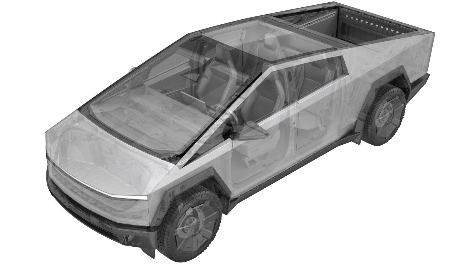
Bi-Cam - Forward Facing (Remove and Install)
 Correction code
1722037021
FRT
0.30
NOTE: Unless
otherwise explicitly stated in the procedure, the above correction code and
FRT reflect all of the work required to perform this procedure, including
the linked procedures. Do
not stack correction codes unless explicitly told to do so.
NOTE: See Flat Rate Times to learn more about FRTs and how
they are created. To provide feedback on FRT values, email ServiceManualFeedback@tesla.com.
NOTE: See Personal Protection
to make sure wearing proper PPE when performing the below procedure.
NOTE: See Ergonomic Precautions for safe and
healthy working practices.
- 2025-07-09: Fixed incorrect images.
- 2024-10-24: Added step to remove overhead console assembly in rearview mirror beauty cover procedure link.
- 2024-03-26: Added step to set vehicle ride height.
Remove
-
Remove the rear view mirror beauty cover. See Beauty Cover - Rearview Mirror (Remove and Install).
NoteIt is not necessary to remove the interior camera from the cover after removal.
-
Release the connector lock, and then
disconnect the GNSS antenna.
- Remove the glare shield from the windshield bracket. See Glare Shield - Rearview Mirror (Remove and Install).
-
Remove the screws (x4) that attach the
forward facing camera assembly to the windshield bracket, and then remove the camera
assembly from the windshield bracket.
 1 Nm (.7 lbs-ft)TIpUse of the following tool(s) is recommended:
- Torx T10 bit
-
Release the connector locks, and then
disconnect the forward facing camera assembly connectors (x2).
Install
-
Use IPA wipes to clean the area inside
the windshield.
NoteAllow 1 minute of dry time.
-
Connect the forward facing camera assembly connectors (x2), and then engage the
connector locks.
-
Position the forward facing camera assembly onto the windshield bracket, and then
install the screws (x4) that attach the camera assembly to the windshield bracket.
 1 Nm (.7 lbs-ft)TIpUse of the following tool(s) is recommended:
- Torx T10 bit
- Install the glare shield from the windshield bracket. See Glare Shield - Rearview Mirror (Remove and Install).
-
Connect the GNSS antenna, and then engage the connector lock.
- Place the vehicle into Service Mode via the UI. See Service Mode.
- Using the vehicle touchscreen, set the vehicle ride height to "Medium".
- Unlock the vehicle gateway. See Gateway (Unlock).
- On the vehicle touchscreen, navigate to Service Mode Plus > Driver Assist > Cameras > Clear Camera Calibration > Run to clear the front facing camera calibration.
- Park the vehicle on a flat surface with at least 106 cm (3.5 ft) of space in front of the front fascia.
-
Set up the target so that the bottom
of the rectangle is 91.4 cm (3 ft) from the ground.
-
Place the target in the appropriate
starting position:
- The checkered portion of the target is facing towards the vehicle.
- The target is centered with the Tesla "T" on the hood.
- The target is placed as close to the front fascia as possible.
-
Make sure that the target is on flat
ground by examining the bubble level on the back of the target.
-
Apply a piece of red tape on the
target so that the top of the tape is 165 cm from the ground.
CAUTIONDo not use existing marks from previous verifications. Remove any existing tape. Measure and reapply new tape to ensure the tape is in the correct location.NoteThe checker pattern on the target is used for vehicles with 1st generation Autopilot. Ignore the checker pattern when affixing the tape.NoteIf the vehicle is equipped with aftermarket suspension components that alter the vehicle ride height, the red tape might have to be adjusted to ensure accurate pitch verification.
- On the vehicle touchscreen, navigate to Service Mode Plus > Driver Assist > Cameras > Camera Preview > Pitch verification > Main camera > Wide Camera to verify front camera pitch.
-
Review the image on the
touchscreen:
NoteThe top of the tape should coincide with the blue horizontal line, If the tape is between the green lines, it is sufficientNoteThe top of the red tape (A) should coincide with the blue horizontal line. However, if the top of the red tape is between the green lines, that is sufficient.
- If the top of the red tape (A) is between the two green lines (B and C), the forward facing camera is within calibration pitch specifications. Go to step 25.
- If the top of the red tape (A) is not between the two green lines (B and C), the forward facing camera needs adjustment. Continue to the next step to adjust the camera.
-
Use a pitch adjustment wrench to
adjust the camera pitch so that the top of the red tape will be between the 2 green
lines.
NoteRotating the wrench clockwise pitches the camera up, and counterclockwise pitches the camera down conversely. 1 full rotation of the wrench can adjust the pitch 0.5 - 1.5 degrees.
-
Review the main and wide images.
- Remove the target from the front of the vehicle.
- Install the rear view mirror beauty cover. See Beauty Cover - Rearview Mirror (Remove and Install).
- Exit Service Mode. See Service Mode.
- Raise the LH front window and close the LH front door.