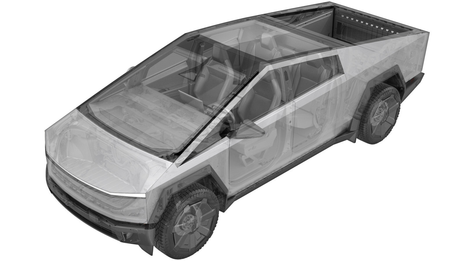
Body Controller - LH (Remove and Replace)
 Correction code
1715017032
FRT
0.84
NOTE: Unless
otherwise explicitly stated in the procedure, the above correction code and
FRT reflect all of the work required to perform this procedure, including
the linked procedures. Do
not stack correction codes unless explicitly told to do so.
NOTE: See Flat Rate Times to learn more about FRTs and how
they are created. To provide feedback on FRT values, email ServiceManualFeedback@tesla.com.
NOTE: See Personal Protection
to make sure wearing proper PPE when performing the below procedure.
NOTE: See Ergonomic Precautions for safe and
healthy working practices.
- 2025-09-09: Readded step for CAN Redeploy.
- 2025-06-05: Removed Redeploy step per latest time study.
- 2025-03-10: Updated post-replacement routines.
- 2024-09-11: Added note and link for testing and servicing Super Connectors.
- 2024-07-03: Added steps to run battery health check.
Remove
- Remove the LH MV controller. See Body Controller - LH (Remove and Install).
Install
- Install the LH MV controller. See Body Controller - LH (Remove and Install).
-
Perform the following
routine using Service Mode or Toolbox (see 0005 - Service Modes):
UPDATE_CAN-REDEPLOYvia Toolbox: (link)via Service Mode Plus:
- Drive Inverter Replacement ➜ Drive Inverter DIRE1L Replacement ➜ CAN Redeploy
- Drive Inverter Replacement ➜ Drive Inverter DIRE1R Replacement ➜ CAN Redeploy
- Drive Inverter Replacement ➜ Drive Inverter DIRE2 Replacement ➜ CAN Redeploy
- Drive Inverter ➜ Front Drive Inverter Replacement ➜ CAN Redeploy
- Drive Inverter ➜ Rear Drive Inverter Replacement ➜ CAN Redeploy
- Drive Inverter ➜ Rear Left Drive Inverter Replacement ➜ CAN Redeploy
- Drive Inverter ➜ Rear Right Drive Inverter Replacement ➜ CAN Redeploy
- Drive Unit ➜ Front Drive Unit Replacement ➜ CAN Redeploy
- Drive Unit ➜ Rear Drive Unit Replacement ➜ CAN Redeploy
- Thermal ➜ HVAC ➜ CAN Redeploy
- chassis ➜ DPB Post Replacement ➜ CAN Redeploy
- chassis ➜ ESP Post Replacement ➜ CAN Redeploy
- chassis ➜ IDB Post Replacement ➜ CAN Redeploy
- chassis ➜ RCU Post Replacement ➜ CAN Redeploy
- chassis ➜ ESP Replacement Panel ➜ CAN Redeploy
- chassis ➜ IBST Replacement Panel ➜ CAN Redeploy
- Perform the following routine using Service Mode or Toolbox (see 0005 - Service Modes): PROC_CONTROLLER_LEFT_POST-REPLACEMENT-PROCEDUREvia Toolbox: (link)via Service Mode Plus: Left Controller ➜ Left Controller Post Replacement ➜ Left Controller Post Replacement Procedure
- Perform the following routine using Service Mode or Toolbox (see 0005 - Service Modes): PROC_VCSEC_C_PAIR-NFC-CARD-V2via Toolbox: (link)via Service Mode: Low Voltage ➜ Keys ➜ Pair Key
- Restore the LH front seat back to its original position.
- Calibrate the headlights. See Headlight - Adjust (Wall Method).
- Place the vehicle into Service Mode. See Service Mode.
- Unlock the vehicle Gateway. See Gateway (Unlock).
-
Learn the MV battery: On the vehicle
touchscreen, tap .
NoteMake sure the routine is successful.
-
Park the vehicle where it can remain
for 30 minutes.
NoteFast charging is not permitted during MV battery health test. Slow charging is permitted.
-
Run Battery Health Test: On the
vehicle touchscreen, tap , and then tap Run and allow the routine to complete.
NoteThe Battery Health Test Required alert will clear after approximately 30 minutes.
- Exit Service Mode. See Service Mode.
- Raise the LH front window and close the LH front door.