Hose - Chiller to HV Battery (LHD) (Dual Motor) (Remove and Replace)
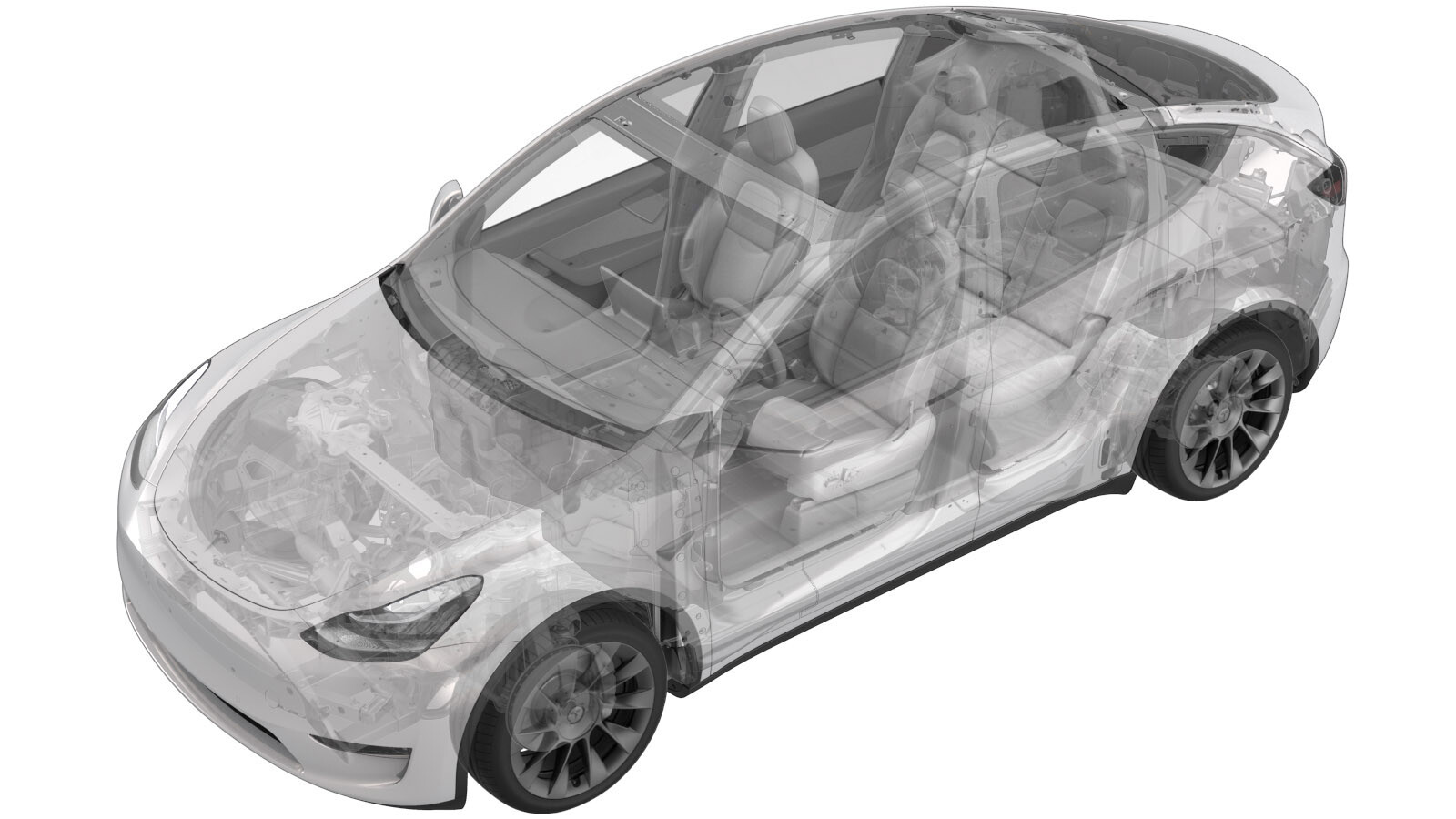 Correction code
18302412
1.02
NOTE: Unless otherwise explicitly
stated in the procedure, the correction code and its associated FRT reflect all of the
work required to perform this procedure, including the linked procedures. Do not stack correction codes unless
explicitly told to do so.
NOTE: See Flat Rate
Times to learn more about FRTs and how they are created.
NOTE: See Personal Protection to make sure wearing proper PPE when
performing the below procedure. NOTE: See Ergonomic Precautions for safe and healthy working
practices.
Correction code
18302412
1.02
NOTE: Unless otherwise explicitly
stated in the procedure, the correction code and its associated FRT reflect all of the
work required to perform this procedure, including the linked procedures. Do not stack correction codes unless
explicitly told to do so.
NOTE: See Flat Rate
Times to learn more about FRTs and how they are created.
NOTE: See Personal Protection to make sure wearing proper PPE when
performing the below procedure. NOTE: See Ergonomic Precautions for safe and healthy working
practices.
- 2026-08-26: Updated procedure: no need for LV battery remove/install, added coolant vacuum refill, added ODIN routines to start and stop thermal fill/drain and updated other minor details.
Remove
- Open the LH front door and lower the window.
- Enable Service Mode. See Service Mode.
-
Perform the following
routine using Service Mode or Toolbox (see 0005 - Service Modes):
PROC_VCFRONT_X_START-THERMAL-FILL-DRAINvia Service Mode:
- Thermal ➜ Actions ➜ Start Thermal Fill/Drain
- Thermal ➜ Coolant System ➜ Start Coolant Fill/Drain
- Thermal ➜ Refrigerant System ➜ Start Refrigerant Fill/Drain
- Drive Unit ➜ Front Drive Unit Replacement ➜ Start Coolant Fill/Drain
- Drive Unit ➜ Rear Drive Unit Replacement ➜ Start Coolant Fill/Drain
- Raise and support the vehicle. See Raise Vehicle - 2 Post Lift.
- Remove the rear underhood apron. See Underhood Apron - Rear (Remove and Replace).
- Remove the underhood storage unit. See Underhood Storage Unit (Remove and Replace).
- Remove the fresh intake duct. See Duct - Fresh Intake (Remove and Replace).
- Disconnect 12V power. See 12V/LV Power (Disconnect and Connect).
-
Release the connector lock, and then
disconnect the electrical sensor for the chiller to battery hose.
- Remove the front aero shield panel. See Panel - Aero Shield - Front (Non-Structural Pack) (Remove and Replace).
- Remove the front skid plate. See Skid Plate - HV Battery - Front (Remove and Replace).
- Put a coolant drain container below the LH front side of the vehicle.
-
Disconnect the HV battery front manifold hose and plug both ends of the hoses.
-
Release the HV battery front manifold hose from the body.
- Remove the coolant drain container from under the vehicle.
- Put a coolant drain pan underneath the vehicle at the car computer area.
-
Put absorbent material under the car
computer coolant hose connections.
-
Release the clip that connects the LH
car computer coolant hose to the car computer coolant port, and then disconnect the
hose.
-
Release the clip that connects the RH
car computer coolant hose to the car computer coolant port, and then disconnect the
hose.
- Plug the car computer coolant ports.
-
Disconnect the chiller to HV battery hose from the supermanifold, and then plug the
supermanifold hose connection.
-
Remove the chiller to HV battery hose
from the vehicle.
NoteRemove the hose through the RH side of the vehicle. Gently maneuver the hose as need to clear any surrounding objects.
Install
-
Install the chiller to HV battery hose
into the vehicle.
NoteFeed the hose into position from the RH side of vehicle along the bulkhead. Gently maneuver the hose as needed to clear surrounding objects.
-
Remove the plug, from the supermanifold and then connect the chiller to HV battery
hose to the supermanifold.
NotePerform a push-pull-push test to make sure that the hose is fully seated.
-
Connect the electrical sensor
connector for the chiller to battery hose, and then engage the connector lock.
NoteThe harness with the purple tape connects to the coolant temperature sensor closest to the coolant bottle.
-
Connect the RH car computer coolant
hose to the car computer coolant port, and then install the clip.
NotePerform a push-pull test to verify that the hose is fully seated.
-
Connect the LH car computer coolant
hose to the car computer coolant port, and then install the clip.
NotePerform a push-pull test to verify that the hose is fully seated.
-
Remove the absorbent towel from under
the car computer coolant connections.
-
Remove the plugs, and then connect the
HV battery front manifold coolant hose.
NotePerform a push-pull test to verify that the hose is fully seated.
-
Install the clip that attaches the HV
battery front manifold hose to the body.
- Remove the coolant drain pan from under the vehicle.
- Install the front skid plate. See Skid Plate - HV Battery - Front (Remove and Replace).
- Remove the front aero shield panel. See Panel - Aero Shield - Front (Non-Structural Pack) (Remove and Replace).
- Perform a coolant vacuum refill. See Cooling System (Vacuum Refill).
- Connect 12V power. See 12V/LV Power (Disconnect and Connect)
-
Perform the following
routine using Service Mode or Toolbox (see 0005 - Service Modes):
PROC_VCFRONT_X_STOP-THERMAL-FILL-DRAINvia Service Mode:
- Thermal ➜ Actions ➜ Stop Thermal Fill/Drain
- Thermal ➜ Coolant System ➜ Stop Coolant Fill/Drain
- Thermal ➜ Refrigerant System ➜ Stop Refrigerant Fill/Drain
- Drive Inverter ➜ Front Drive Inverter Replacement ➜ Stop Fluid Fill/Drain
- Drive Inverter ➜ Rear Drive Inverter Replacement ➜ Stop Fluid Fill/Drain
- Drive Inverter ➜ Rear Left Drive Inverter Replacement ➜ Stop Fluid Fill/Drain
- Drive Inverter ➜ Rear Right Drive Inverter Replacement ➜ Stop Fluid Fill/Drain
- Drive Unit ➜ Front Drive Unit Replacement ➜ Stop Coolant Fill/Drain
- Drive Unit ➜ Rear Drive Unit Replacement ➜ Stop Coolant Fill/Drain
-
Perform the following
routine using Service Mode or Toolbox (see 0005 - Service Modes):
TEST_VCFRONT_X_THERMAL-COOLANT-AIR-PURGEvia Service Mode:
- Thermal ➜ Actions ➜ Coolant Purge Stop or Coolant Purge Start
- Thermal ➜ Coolant System ➜ Coolant Purge Start
- Drive Inverter ➜ Front Drive Inverter Replacement ➜ Coolant Air Purge
- Drive Inverter ➜ Rear Drive Inverter Replacement ➜ Coolant Air Purge
- Drive Inverter ➜ Rear Left Drive Inverter Replacement ➜ Coolant Air Purge
- Drive Inverter ➜ Rear Right Drive Inverter Replacement ➜ Coolant Air Purge
- Drive Unit ➜ Front Drive Unit Replacement ➜ Coolant Air Purge
- Drive Unit ➜ Rear Drive Unit Replacement ➜ Coolant Air Purge
- Inspect the coolant level and top off as required.
- Install the fresh intake duct. See Duct - Fresh Intake (Remove and Replace).
- Install the HEPA filter assembly. See Assembly - Filter - HEPA (Remove and Replace).
- Install the underhood storage unit. See Underhood Storage Unit (Remove and Replace).
- Install the rear underhood apron. See Underhood Apron - Rear (Remove and Replace).
- Exit Service Mode. See Service Mode.