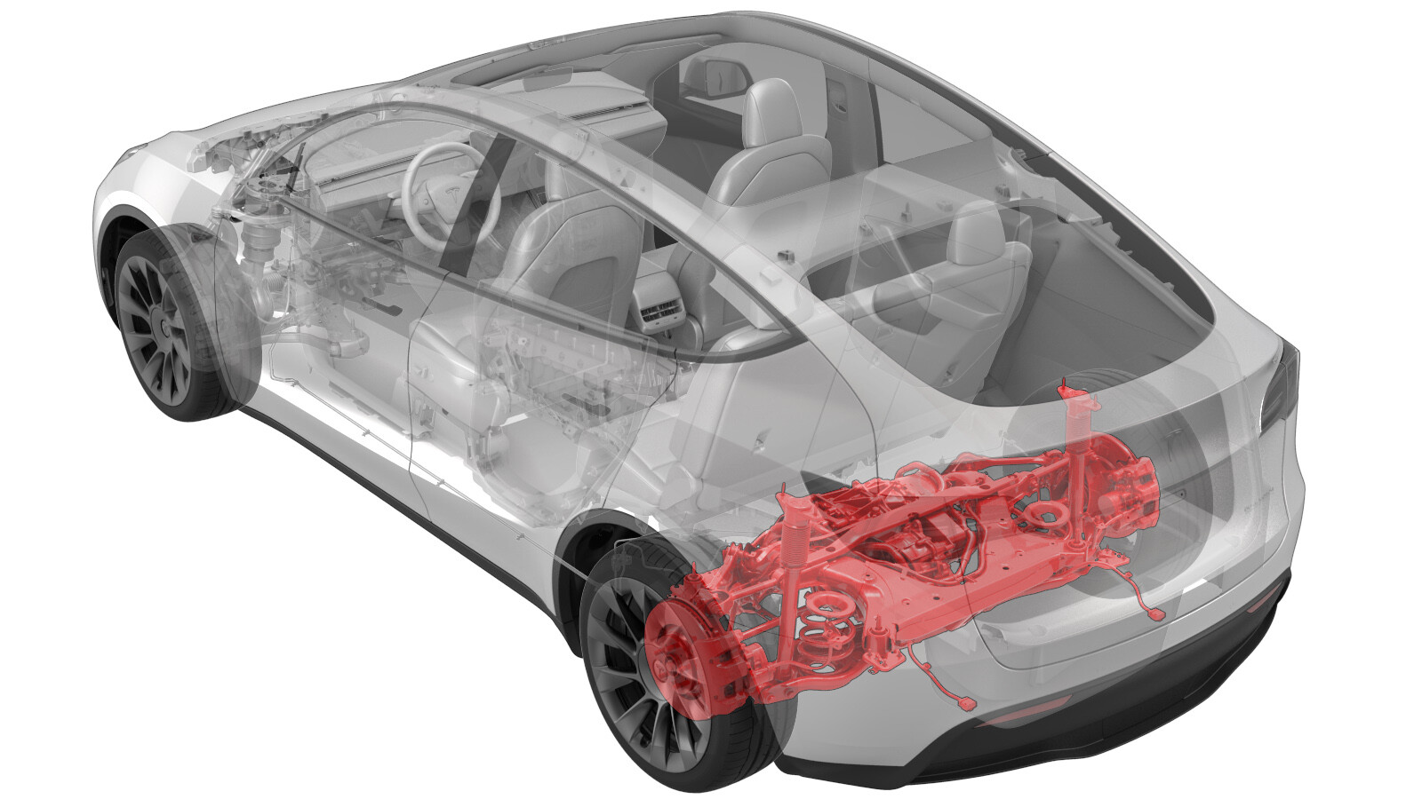
Subframe Assembly - Rear (Remove and Install)
 Correction code
30010201
2.22
NOTE: Unless otherwise explicitly
stated in the procedure, the above correction code and FRT reflect all of the work
required to perform this procedure, including the linked procedures. Do not stack correction codes unless
explicitly told to do so.
NOTE: See Flat Rate
Times to learn more about FRTs and how they are created.
NOTE: See Personal Protection to make sure wearing proper PPE when
performing the below procedure. NOTE: See Ergonomic Precautions for safe and healthy working
practices.
Correction code
30010201
2.22
NOTE: Unless otherwise explicitly
stated in the procedure, the above correction code and FRT reflect all of the work
required to perform this procedure, including the linked procedures. Do not stack correction codes unless
explicitly told to do so.
NOTE: See Flat Rate
Times to learn more about FRTs and how they are created.
NOTE: See Personal Protection to make sure wearing proper PPE when
performing the below procedure. NOTE: See Ergonomic Precautions for safe and healthy working
practices.
- 2026-01-29: Added photos to show how to position the subframe lifting tool.
- 2025-12-12: Updated torque table and torque values shown in the procedure.
- 2025-02-14: Added rear suspension torque check.
- 2024-10-14: Updated torque spec for LH/RH shear plate-to-rear subframe large bolts.
- 2023-06-15: Added shear plate small bolts torque figure for Structural Pack vehicles.
Equipment:
- 1134520-00-A Kit, EPB Release, Handheld
- 1129348-00-A XP-10 Power Supply, XP-10
- 1099645-00-B Fixture, Subframe, Model 3
- 1140311-00-A Lever Lock, HV Connector, Model 3
Torque Specifications
| Description | Torque Value | Recommended Tools | Reuse/Replace | Notes |
|---|---|---|---|---|
| Bolts that attach the LH rear brake caliper bracket to the knuckle |
 83 Nm (61.2 lbs-ft) |
|
Replace | |
| Bolts that attach the LH rear damper at the top mount |
 41 Nm (30.2 lbs-ft) |
|
Reuse | |
| Nut that attaches the rear drive unit ground strap to the body |
 10 Nm (7.4 lbs-ft) |
|
Reuse | |
| Nuts that attach the HV battery to rear drive unit harness bracket to the HV battery |
 10 Nm (7.4 lbs-ft) |
|
Reuse | |
| Small bolts that attach the LH shear plate to the HV battery (non-Structural Pack vehicles) |
 35 Nm (25.8 lbs-ft) |
|
Reuse |
Note Some vehicles
are equipped with self-tapping bolts in bolt position #8-15 from the
factory. If the vehicle is equipped with a bolt with a hexagonal
indentation on the bolt head (1637725-00-A), the torque value is 64 Nm. |
| Small bolts that attach the LH shear plate to the HV battery (Structural Pack vehicles) |
62 Nm (45.7 lbs-ft) |
|
||
| Large bolt that attaches the LH shear plate and rear subframe to the body |
 130 Nm (95.9 lbs-ft) |
|
Replace | |
| Bolts that attach the rear subframe to the body |
 165 Nm (121.7 lbs-ft) |
|
Replace |
Remove
- Raise and support the vehicle. See Raise Vehicle - 2 Post Lift.
- Open all doors and lower the windows.
- Release the parking brakes. See Parking Brake - Caliper - Rear - LH (Release).
- Remove the 2nd row lower seat cushion. See Seat Cushion - Lower - 2nd Row (Remove and Replace).
- Remove the rear underhood apron. See Underhood Apron - Rear (Remove and Replace).
- Disconnect 12V power. See 12V/LV Power (Disconnect and Connect).
- Perform the vehicle electrical isolation procedure. See Vehicle HV Disablement Procedure.
- Remove the LH and RH rear wheels. See Wheel Assembly (Remove and Install).
- Remove the LH and RH suspension cover. See Cover - Rear Suspension - LH (Remove and Replace).
- Remove the mid aero shield panel. See Panel - Aero Shield - Rear (Remove and Replace).
- Remove the rear fascia diffuser. See Diffuser - Rear Fascia (Remove and Replace).
-
Remove the nut that attaches the rear drive unit ground strap to the body.
TIpUse of the following tool(s) is recommended:
- 10 mm 12-point deep socket
-
Remove and discard the bolt that attaches the LH rear brake caliper bracket to the knuckle, and then hang the caliper bracket on the body with an S-hook. Repeat this step on the RH rear brake caliper.
TIpUse of the following tool(s) is recommended:
- External Torx E18
-
Install a spring compressor onto the LH rear coil spring.
TIpUse of the following tool(s) is recommended:
- Gedore Spring Compressor
-
Remove the bolts (x2) that attach the LH rear damper to the top mount.
TIpUse of the following tool(s) is recommended:
- 15 mm socket
- 3 in extension
- Repeat steps 14 and 15 on the RH rear damper.
-
Disconnect the electrical harness from the LH 12V subframe connector.
-
Release the clip that attaches the LH subframe electrical harness to the body.
- Repeat steps 17 and 18 on the RH side of the vehicle.
- Remove the rear stabilizer bar. See Stabilizer Bar - Rear (Remove and Replace).
- Remove the rear HV battery skid plate. See Skid Plate - HV Battery - Rear (Remove and Replace).
- Position a coolant drain container under the LH rear of the HV battery.
-
Disconnect the rear drive unit inverter inlet hose from the LH rear side of the HV battery, and then plug the male and female fittings.
- If the rear drive unit will be removed from the rear subframe assembly, continue to step 25. If the rear drive unit will not be removed, skip to step 27.
- Position the coolant drain container beneath the LH rear drive unit area.
-
Disconnect the coolant inlet hose from the rear drive unit, and then plug the hose.
- Position the coolant drain under the RH rear of the vehicle.
- Release the push clips (x2) that attach the RH rear wheel liner to the rocker panel.
-
Release the clip, disconnect the rear drive unit coolant outlet hose to powertrain return hose, and then plug the male and female fittings.
- Remove the coolant drain container from under the vehicle.
-
Remove the nut that attaches the HV battery to rear drive unit harness bracket to the HV battery.
TIpUse of the following tool(s) is recommended:
- 10 mm socket
- 4 in extension
-
Slide the release to unlock the HV battery rear drive unit connector handle of the rear drive unit to HV battery harness from the secured position.
-
Fully raise the handle on the HV battery rear drive unit connector, and then remove the HV battery rear drive unit connector from the HV battery header.
-
Position the subframe lifting tool
under the rear subframe.
-
Attach an air hose to the subframe lifting tool.
-
With an assistant, raise the subframe lifting tool to support the rear subframe.
-
Loop the straps over the rear subframe, hook the ends of the straps to the metal rings, and then pull the straps tight to restrain the subframe to the rear subframe lifting tool.
NoteLower the vehicle to give more slack to connect the straps to the rings, if necessary.
-
Mark the LH and RH rear subframe bolts for realignment during re installation.
NoteYou can also mark the LH and RH subframe casting and subframe bushing to the body.
-
Release the fir tree clips that attach the coolant hoses to the LH shear plate.
-
Remove the smaller bolts that attach the LH shear plate to the HV battery.
TIpUse of the following tool(s) is recommended:
- 13 mm socket
- 3 in extension
-
Remove the larger bolt that attaches the LH shear plate and rear subframe to the body, and then remove the LH shear plate.
TIpUse of the following tool(s) is recommended:
- 21 mm socket
- 6 in extension
- Repeat step 39 through step 41for the RH shear plate.
-
Remove and discard the bolts (x2) that attach the rear subframe to the body.
TIpUse of the following tool(s) is recommended:
- 21 mm socket
- 6 in extension
-
With an assistant, slowly lower the subframe lifting tool to remove the rear subframe from the vehicle.
CAUTIONTake care not to damage HV harnesses and coolant hoses during lowering of the subframe.
- Disconnect the air supply from the rear subframe lifting tool.
-
Move the rear subframe and subframe lifting tool away from the vehicle.
Install
- Position the subframe lifting tool and rear subframe underneath the vehicle.
- Connect the air line to the subframe lifting tool.
-
With an assistant, slowly raise the rear drive unit and subframe into position.
CAUTIONTake care not to damage HV harnesses and coolant hoses during lifting of the subframe.
-
Hand-tighten new bolts (x2) that attach the rear subframe to the body.
NoteThe tightening of the bolts will be performed later in this procedure.
-
Install the LH shear plate to the rear subframe and HV battery, and then hand-tighten the bolt that attaches the shear plate to the subframe.
NoteThe tightening of the bolt will be performed later in this procedure.
-
Hand-tighten the smaller bolts that attach the LH shear plate to the HV battery.
NoteThe tightening of the bolts will be performed later in this procedure.
- Repeat steps 5 and 6 on the RH shear plate.
-
Position the subframe to the locations as marked during removal.
NoteReturn the subframe to its original position as closely as possible.
-
Torque the bolts that attach the LH
and RH rear subframe to the body, and then mark them with a paint pen after
torquing.165 Nm (121.7 lbs-ft)TIpUse of the following tool(s) is recommended:
- 21 mm socket
- 6 in extension
-
Torque the large bolts that attach the
LH and RH shear plates to the vehicle, and then mark them with a paint pen after
torquing.130 Nm (95.9 lbs-ft)TIpUse of the following tool(s) is recommended:
- 21 mm socket
- 6 in extension
-
Torque the smaller bolts that attach the LH and RH shear plates to the vehicle.
For non-Structural Pack vehicles:35 Nm (25.8 lbs-ft)For Structural Pack vehicles:62 Nm (45.7 lbs-ft)TIpUse of the following tool(s) is recommended:
- 13 mm socket
- 3 in extension
-
Fasten the fir tree clips that attach the coolant hoses to the LH and RH shear plates.
LH shear plate shown, RH shear plate similar
- Release the straps and lower the subframe lifting tool.
- Disconnect the air line from the subframe lifting tool, and then remove the tool from under the vehicle.
-
Fully raise the handle on the HV battery rear drive unit connector of the rear drive unit to HV battery harness.
-
Install the HV connector special tool onto the HV battery rear drive unit connector.
-
Use both hands to firmly connect the HV battery rear drive unit connector of the rear drive unit to HV battery harness to the HV battery header.
CAUTIONMake sure that the connector fits the header squarely and tightly, and that both retention pins enter the handle.
- Remove the HV connector special tool from the HV battery rear drive unit connector.
-
While pressing the HV battery rear drive unit connector onto the HV battery header, fully lower the handle.
CAUTIONMake sure that the handle does not bind as it is lowered.
-
Slide the release to lock the HV battery rear drive unit connector handle in the secured position.
-
Verify that the HV battery rear drive unit connector is fully seated, and compare both sides of the connector that it is properly secured in place.
NoteAn improperly seated connector might lead to connector damage and rear drive unit problems later on.
-
Install the nut that attaches the rear
drive unit HV electrical harness bracket to the HV battery.10 Nm (7.4 lbs-ft)TIpUse of the following tool(s) is recommended:
- 10 mm socket
- 4 in extension
- Position a coolant drain container under the RH rear of the HV battery.
-
Remove the hose plugs, connect the rear drive unit outlet hose to the powertrain return hose, and then fasten the clip.
CAUTIONPerform a push-pull test to verify that the hose is fully seated.
- Position the coolant drain beneath the LH rear of the HV battery.
-
Remove the plugs from the male and female fittings, connect the rear drive unit inverter inlet hose to the rear of the HV battery, and then fasten the clip.
CAUTIONPerform a push-pull test to verify that the hose is fully seated.
- Remove the coolant drain from beneath the vehicle.
- Install the rear HV battery skid plate. See Skid Plate - HV Battery - Rear (Remove and Replace).
- Install the rear stabilizer bar. See Stabilizer Bar - Rear (Remove and Replace).
-
Fasten the LH subframe electrical harness barrel clip to the body.
-
Connect the electrical connector for the LH side 12V subframe harness.
Figure 1. LH side shown, RH similar - Repeat steps 30 and 31 on the RH side of the vehicle.
-
Install the bolt that attaches the
rear drive unit ground strap to the body.10 Nm (7.4 lbs-ft)TIpUse of the following tool(s) is recommended:
- 10 mm 12-point deep socket
NoteReinstall the washer if the vehicle had this washer during removal. -
Install the bolts that attach the RH
rear damper at the top mount.41 Nm (30.2 lbs-ft)TIpUse of the following tool(s) is recommended:
- 15 mm socket
- 3 in extension
LH shown; RH similar.
-
Remove the spring compressor from the RH rear coil spring.
-
Install the RH rear brake caliper
bracket onto the knuckle, and then install the bolts that attach the caliper bracket to
the knuckle.83 Nm (61.2 lbs-ft)TIpUse of the following tool(s) is recommended:
- External Torx E18
LH rear brake caliper shown, RH rear brake caliper similar.
- Repeat step 34through step 36 for the LH side of the vehicle.
- Check the torque for any rear suspension bolts that were loosened while the rear subframe assembly was removed from the vehicle and torque as required. See Suspension - Rear (Check Torque).
- Install the rear fascia diffuser. See Diffuser - Rear Fascia (Remove and Replace).
- Install the clips that attach the LH and RH wheel liner to the rear fascia.
- Install the mid aero shield panel. See Panel - Aero Shield - Rear (Remove and Replace).
- Install the LH and RH rear suspension covers. See Cover - Rear Suspension - LH (Remove and Replace).
- Install the LH and RH rear wheels. See Wheel Assembly (Remove and Install).
- Remove the coolant bottle cap, and then fill the coolant bottle to the "MAX" line.
- Connect 12V power. See 12V/LV Power (Disconnect and Connect).
- Press and hold the Park button on the gear selector to release the EPB service mode.
-
Perform the following
routine using Service Mode or Toolbox (see 0005 - Service Modes):
TEST-SELF_VCFRONT_X_THERMAL-PERFORMANCEvia Service Mode:Thermal ➜ Actions ➜ Test Thermal Performancevia Service Mode Plus:
- Drive Inverter ➜ Front Drive Inverter Replacement ➜ Thermal System Test
- Drive Inverter ➜ Rear Drive Inverter Replacement ➜ Thermal System Test
- Drive Inverter ➜ Rear Left Drive Inverter Replacement ➜ Thermal System Test
- Drive Inverter ➜ Rear Right Drive Inverter Replacement ➜ Thermal System Test
- Drive Unit ➜ Front Drive Unit Replacement ➜ Thermal System Test
- Drive Unit ➜ Rear Drive Unit Replacement ➜ Thermal System Test
-
Inspect the coolant level and top off as necessary, and then install the coolant bottle cap.
NoteEnsure that the coolant level is at the "MAX" line.
- Install the rear underhood apron. See Underhood Apron - Rear (Remove and Replace).
- Install the 2nd row lower seat cushion. See Seat Cushion - Lower - 2nd Row (Remove and Replace).
- Restore the driver and front passenger seats back to their original positions.
- Refer to the Alignment Requirement tables to determine whether an EPAS alignment check (EC) or four wheel alignment check (AC) is necessary. If performed, add the alignment check/adjust correction code as a separate activity to the SV. See Alignment Requirement - Suspension.