2026-06-30
Cover - Ancillary Bay (Remove and Install)
 Correction code
16101001
1.08
NOTE: Unless otherwise explicitly
stated in the procedure, the above correction code and FRT reflect all of the work
required to perform this procedure, including the linked procedures. Do not stack correction codes unless
explicitly told to do so.
NOTE: See Flat Rate
Times to learn more about FRTs and how they are created.
NOTE: See Personal Protection to make sure wearing proper PPE when
performing the below procedure. NOTE: See Ergonomic Precautions for safe and healthy working
practices.
Correction code
16101001
1.08
NOTE: Unless otherwise explicitly
stated in the procedure, the above correction code and FRT reflect all of the work
required to perform this procedure, including the linked procedures. Do not stack correction codes unless
explicitly told to do so.
NOTE: See Flat Rate
Times to learn more about FRTs and how they are created.
NOTE: See Personal Protection to make sure wearing proper PPE when
performing the below procedure. NOTE: See Ergonomic Precautions for safe and healthy working
practices.
- 2026-06-10: Added information for Service Cover (EMEA only)
- 2025-10-13: Added warning at step to remove/install the ancillary bay cover to do this while standing outside the vehicle.
- 2024-04-04: Added information on installing and removing ancillary bay kit insulators.
- 2023-06-09: Corrected paint pen colors.
- 2023-05-22: Added caution for correct positive DC cable connection.
Equipment:
- 1127845-00-A Asy, Service Cover, Penthouse, Model 3
- 1059330-00-B Skt, 1/4in Dr, 5-Lobe Torx Plus External
- 1076971-02-A Wrench, Torque + Angle, 1/4" Dr
- 1108272-00-B Cap, Logic Conn, Inv, 3DU
Warning
Remove
all jewelry (watches, bracelets, rings, necklaces, earrings, ID tags, piercings, etc.)
from your person, and all objects (keys, coins, pens, pencils, tools, fasteners, etc.)
from your pockets before performing any procedure that exposes you to high
voltage.
Warning
If
corrective eyewear is necessary to safely perform any procedure, make sure that the
eyewear is securely restrained to the head and cannot fall
off.
Warning
Only
technicians who have completed all required certification courses are permitted to
perform this procedure. Tesla recommends third party service provider technicians
undergo equivalent training before performing this procedure. For more information on
Tesla Technician requirements, or descriptions of the subject matter for third parties,
see HV Certification Requirements. Proper personal protective equipment (PPE) and insulating HV
gloves with a minimum rating of class 0 (1000V) must
be worn at all times a high voltage cable, busbar, or fitting is handled. Refer to Tech Note TN-15-92-003,
High Voltage Awareness Care Pointsfor additional safety information.
Warning
When servicing the
ancillary bay cover and components in or around the ancillary bay, there is a
possibility of encountering metal flashing on the inner edge of the vehicle
single-piece rear casting. These sharp protrusions are a cut hazard, and proper PPE
should be worn if there is a chance of contacting the flashing unprotected. If not
already wearing leather over gloves, then at least wear cut-resistant gloves when
the flashing is present.
Torque Specifications
| Description | Torque Value | Recommended Tools | Reuse/Replace | Notes |
|---|---|---|---|---|
| Nut that attaches the positive 12V output cable to the DCDC passthrough |
 9 Nm (6.6 lbs-ft) |
|
Replace | 1523698-00-A |
| Bolts that attach the ancillary bay cover to the high voltage controller |
5 Nm (3.7 lbs-ft) +30 deg |
|
Reuse | |
| Bolt attaches the ancillary bay cover to the HV battery |
8 Nm (5.9 lbs-ft) |
|
Reuse |
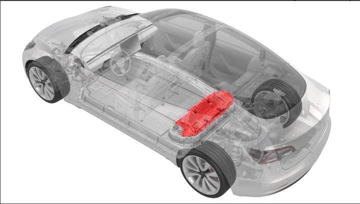
Remove
- Remove the 2nd row lower seat cushion. Seat Cushion - Lower - 2nd Row (Remove and Replace).
- Remove the RH 2nd row seat back. See Seat Back - 2nd Row - RH (Remove and Replace).
- Remove the LH 2nd row seat back. See Seat Back - 2nd Row - LH (Remove and Replace).
- Disconnect 12V power. See 12V/LV Power (Disconnect and Connect).
- Perform Vehicle HV Disablement Procedure. See Vehicle HV Disablement Procedure.
-
Disconnect the electrical
harness from the high voltage controller connector.
NoteThe HV battery positive contactor and negative contactor open with a clunk sound.
-
Install the logic connector
cap onto the high voltage controller connector to prevent mistaken
reconnection and protect the connector.
- If the leather over gloves have been removed, inspect the inner edge of the vehicle single-piece rear casting for flashing. If flashing is present, put on cut-resistant gloves.
- Release the cover on the positive 12V output cable, at the DCDC passthrough.
-
Remove and discard the nut
that attaches the positive 12V output cable to the DCDC passthrough, and
then remove the cable from the passthrough.
NoteInspect the condition of the rubber boot at the end of the output cable, and replace the boot if it is melted or damaged.TIpUse of the following tool(s) is recommended:
- 13 mm 12-point deep socket
-
Remove the bolts that attach
the high voltage controller internally to the ancillary bay cover.
TIpUse of the following tool(s) is recommended:
- External Torx E10
Figure 1. 4-Bolt HVC Ancillary Bay Cover Figure 2. 3-Bolt HVC Ancillary Bay Cover -
Remove the bolts that attach
the ancillary bay cover to the HV battery, and remove the ancillary bay
cover from the vehicle.
WarningRemove the ancillary bay cover from the vehicle while standing outside the vehicle to reduce the risk of falling into the open HV battery.CAUTIONUse an External Torx E10 5-Lobe socket that is not magnetized. Sockets with magnets will not fully grip and can possibly strip the bolt head.NoteThe bolts are captive to the ancillary bay cover.TIpUse of the following tool(s) is recommended:
- External Torx E10 5-Lobe
-
Visually inspect the
interior of the ancillary bay for insulators on the high voltage
components.
- If any of the insulators are missing, install the missing insulators. See Insulators - HV Battery (Install and Remove).
- If all of the insulators are installed, continue to the procedure that required the ancillary bay cover to be removed.
CAUTIONFor EMEA only: Install a Service Cover on the Ancillary Bay if required due to training requirements. E.g. for pyrotechnic disconnect replacement by technicians who are not certified for all Ancillary Bay procedures.
Install
- Use an IPA wipe to clean any residue from the high voltage controller mounting bolt holes and both the inside and outside of the ancillary bay cover at the bolt holes.
- Use IPA wipes to clean the ancillary bay cover gasket surface, and the mating surface of the HV battery.
-
If the aluminum tape
retrofit patch is missing or damaged, remove the patch (if present), clean
the area with an IPA wipe, apply another patch of aluminum tape, and wet out
the patch with a silicone roller to set the adhesive.
TIpUse of the following tool(s) is recommended:
- 3M 425 Aluminum Foil Tape - 0601363
Figure 3. 5-Bolt to 4-Bolt Patch 50mm x 50mm Figure 4. 4-Bolt to 3-Bolt Patch 30mm x 30mm - Inspect the inner edge of the vehicle single-piece rear casting for metal flashing. If flashing is present and the leather over gloves have been removed, put on cut-resistant gloves.
-
Inspect ancillary bay walls for damage.
NoteAny dent or depression in the seal that causes it to not be flat will result in a leak, and cannot be reused. Any paint that comes off the ancillary bay wall, whether or not it sticks to the seal, will require enclosure leak test when reassembled.
-
Inspect the ancillary bay
cover seal to confirm it has no visual damage.
NoteImage up close for clarity. Delaminated and torn seals cannot be reused.
-
Install the ancillary bay
cover to the HV battery.
WarningInstall the ancillary bay cover to the HV battery while standing outside the vehicle to reduce the risk of falling into the open HV battery.
-
Install the logic connector
cap onto the high voltage controller connector.
-
Install the ancillary bay
cover bolts in the sequence shown, and mark each with an orange paint pen as
they are torqued.8 Nm (5.9 lbs-ft)CAUTIONUse an External Torx E10 5-Lobe socket that is not magnetized. Sockets with magnets will not fully grip and can possibly strip the bolt head.TIpUse of the following tool(s) is recommended:
- External Torx E10 5-Lobe
Figure 5. 18-Bolt Ancillary Bay Cover Torque Sequence - Remove the HV insulating gloves.
-
Install the high voltage
controller to ancillary bay cover bolts in the sequence shown, and mark each
bolt with an orange paint pen as they are torqued.5 Nm (3.7 lbs-ft) +30 degCAUTIONInsufficient torque of bolts 1 and 2 opens the high voltage interlock loop circuit.TIpUse of the following tool(s) is recommended:
- External Torx E10
Figure 6. 4-Bolt HVC Ancillary Bay Cover Figure 7. 3-Bolt HVC Ancillary Bay Cover -
Connect the positive 12V
output cable to the DCDC passthrough, install a new nut to attach the cable,
and mark the nut with a pink/violet paint pen after torque.9 Nm (6.6 lbs-ft)CAUTIONMake sure that the rubber boot is not trapped under the cable lug or pinched between the cable lug and nut.CAUTIONMake sure the positive output cable is positioned properly and in the right direction against the plastic anti-rotation edge on the DCDC passthrough.NoteMark the fastener with a paint pen after torquing.TIpUse of the following tool(s) is recommended:
- 13 mm 12-point deep socket
-
Install the positive 12V
output cover.
-
Remove the logic connector
cap from the high voltage controller connector.
-
Connect the electrical
harness to the high voltage controller connector.
- If damage was found on the ancillary bay cover gasket or the HV battery mating surface, or if the aluminum tape retrofit patch was replaced, or if another procedure instructed to perform an ancillary bay air leak test, do that now. See GUID-91A861A3-8448-475C-907E-F4085A78F3AC.html#GUID-91A861A3-8448-475C-907E-F4085A78F3AC.
- Install the LH 2nd row seat back. See Seat Back - 2nd Row - LH (Remove and Replace).
- Install the RH 2nd row seat back. See Seat Back - 2nd Row - RH (Remove and Replace).
- Install the 2nd row lower seat cushion. See Seat Cushion - Lower - 2nd Row (Remove and Replace).
- Connect 12V power. See 12V/LV Power (Disconnect and Connect).