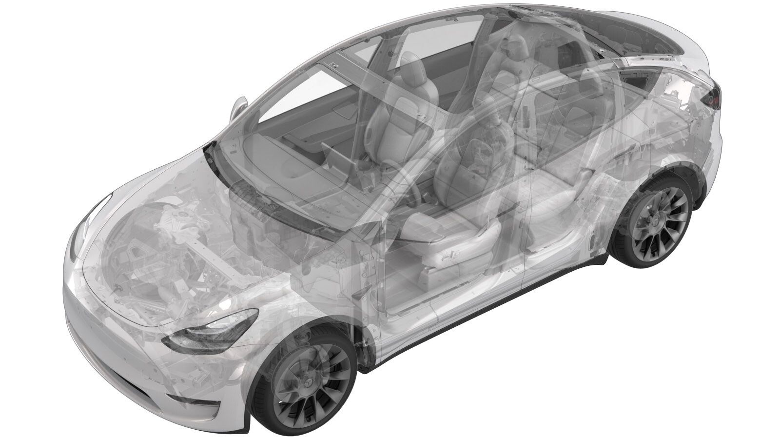
Ferrite - Shunt Harness - Ancillary Bay - HV Battery (Structural Pack) (Retrofit)
 Correction code
16305026
1.80
NOTE: Unless otherwise explicitly
stated in the procedure, the above correction code and FRT reflect all of the work
required to perform this procedure, including the linked procedures. Do not stack correction codes unless
explicitly told to do so.
NOTE: See Flat Rate
Times to learn more about FRTs and how they are created. To provide feedback on
FRT values, email ServiceManualFeedback@tesla.com.
NOTE: See Personal Protection to make sure wearing proper PPE when
performing the below procedure. See Ergonomic Precautions for safe and healthy working practices.
- 2023-12-14: Updated note about revisions.
Equipment:
- 2019928-00-A YSB, PH, FERRITE 46 ROUND CABLE CORE ASS
- 1922330-00-A TAPE, PET FLEECE, RUBBER
Procedure
- Remove the ancillary bay cover. See Cover - Ancillary Bay (Structural Pack) (3-Phase) (Remove and Replace).
-
Remove the pyro disconnect
insulators (x2).
-
Remove the bolts (x2) that
attach the pyrotechnic battery disconnect to the ancillary bay.
Note2x bolts, discard after removal.
-
Remove the pyrotechnic
battery disconnect from the ancillary bay.
-
Release the securing tab from the pyrotechnic battery disconnect connector,
and then disconnect the connector.
- Install the pyrotechnic battery disconnect dummy cover.
-
Disconnect the shunt
harness, and loosen the clips (x2) that attach the shunt harness to the HV
battery trim.
-
Release the connectors (x2) and clips (x2) of the ancillary bay harness between
the PCS and the negative contactor.
-
Remove the leather outer
gloves.
CAUTIONThis is a one-time exception to remove only the leather gloves for the next three steps. Make sure the HV gloves are not damaged during rework.
-
Apply a piece of tape to the first 50 mm of the ancillary bay harness, starting
at the location where the shunt harness is attached.
-
Install the clip-on ferrite to the shunt harness, as close as possible to
the ancillary bay harness.
NoteRotate the clip-on ferrite around the harness to confirm the ferrite is installed correctly and does not pinch the harness.
-
Apply tape onto the clip-on ferrite and the ancillary bay harness to prevent
movement of the ferrite.
-
Put on the leather outer gloves.
CAUTIONRemoval of the leather outer gloves is only permitted for installing the clip-on ferrite and applying the tape. Do not perform the rest of this procedure without leather outer gloves.
-
Reconnect the connectors of the ancillary bay harness between the PCS and the
negative contactor, and then fasten the clips (x2) of the ancillary bay
harness.
-
Connect the shunt harness, and fasten the clips (x2) that attach the shunt
harness to the plastic HV battery trim.
- Remove the pyrotechnic battery disconnect dummy cover.
-
Connect the pyrotechnic battery disconnect connector.
-
Use an IPA wipe to clean the
HV mating surfaces of the shunt, busbar, and the pyrotechnic battery
disconnect, and allow at least 1 minute to fully dry.
-
Set the multimeter to the
"LoZ" (low impedance) mode.
NoteFor Fluke multimeters without "LoZ" mode on the mode selector, see Multimeter (LoZ Setting).
-
Measure the voltage between
the shunt (left) and busbar (right) for at least 10 seconds, so as to
balance the voltage across the pyrotechnic battery disconnect mount
points.
NoteThe voltage displayed on the multimeter is not as important as balancing the mount points.
-
Position the pyrotechnic
battery disconnect into the ancillary bay, align the pins of the connector with
the disconnect, and then press the disconnect straight down onto the
busbars.
-
Install bolts securing pyro
disconnect to ancillary bay.
Note2x patch bolts, 13mm, 5 Nm +60 degrees, Install new fasteners.
-
Measure resistance from pyro
disconnect to busbar (right).
Note1x HV joint, 0.060 mΩ (60 μΩ) or less, Verify Hioki tester is properly zeroed before usage, If the impedance is higher, escalate a Toolbox session, as appropriate.
-
Measure resistance from the
pyro disconnect to shunt (left).
Note1x HV joint, 0.045 mΩ (45 μΩ) or less, Verify Hioki tester is properly zeroed before usage, If the impedance is higher, escalate a Toolbox session, as appropriate.
-
Install the pyro disconnect
insulators.
Note2x insulators.
- Install the ancillary bay cover. See Cover - Ancillary Bay (Structural Pack) (3-Phase) (Remove and Replace).