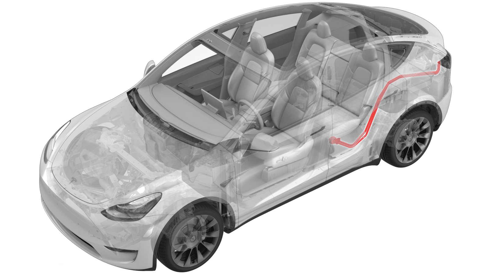
Busbars - Charge Port to HV Battery (Remove and Replace)
 Correction code
44013102
0.84
NOTE: Unless otherwise explicitly
stated in the procedure, the above correction code and FRT reflect all of the work
required to perform this procedure, including the linked procedures. Do not stack correction codes unless
explicitly told to do so.
NOTE: See Flat Rate
Times to learn more about FRTs and how they are created.
NOTE: See Personal Protection to make sure wearing proper PPE when
performing the below procedure. NOTE: See Ergonomic Precautions for safe and healthy working
practices.
Correction code
44013102
0.84
NOTE: Unless otherwise explicitly
stated in the procedure, the above correction code and FRT reflect all of the work
required to perform this procedure, including the linked procedures. Do not stack correction codes unless
explicitly told to do so.
NOTE: See Flat Rate
Times to learn more about FRTs and how they are created.
NOTE: See Personal Protection to make sure wearing proper PPE when
performing the below procedure. NOTE: See Ergonomic Precautions for safe and healthy working
practices.
- 2023-10-10: Added a caution to not manually close the charge port door.
Equipment:
- 1076921-00-A Insulation Multimeter, Fluke 1587 (EMEA)
- 1076921-01-B Insulation Multimeter, Fluke 1508 (APAC)
- 1130480-00-A Test Probes, Slim, Fluke TP38
Only
technicians who have completed all required certification courses are permitted to
perform this procedure. Tesla recommends third party service provider technicians
undergo equivalent training before performing this procedure. For more information on
Tesla Technician requirements, or descriptions of the subject matter for third parties,
see HV Certification Requirements. Proper personal protective equipment (PPE) and insulating HV
gloves with a minimum rating of class 0 (1000V) must
be worn at all times a high voltage cable, busbar, or fitting is handled. Refer to Tech Note TN-15-92-003, High Voltage Awareness
Care Points
for additional safety
information.
Remove all jewelry (watches, bracelets, rings, necklaces, earrings, ID tags, piercings, etc.) from your person, and all objects (keys, coins, pens, pencils, tools, fasteners, etc.) from your pockets before performing any procedure that exposes you to high voltage.
Proper Personal Protective Equipment (PPE) is required to perform this procedure:
- High Voltage (HV) insulating gloves
- Leather glove protectors
- High voltage glove tester
- Safety glasses
- Electrical hazard rated safety shoes
A glove inflator is the only recommended way to test HV gloves. Both HV gloves must pass testing before beginning this procedure. If either glove does not pass the air check, discard the pair.
- North America: HV gloves can be used up to 12 months after the testing date printed on the glove, but only 6 months after first use even if the gloves are still within the 12 month period. If the gloves were not put into service during the 12-month period following the testing date, they must be retested before being put into service.
- Europe: Class 0 (1000V) HV gloves have no expiration date and may be used if they pass the pre-use assessment and the periodic inspection.
- Asia Pacific: Follow the
expiration date stated by the HV glove manufacturer, and:
- o China only: Test the gloves every 6 months according to GB/T 17622.
Torque Specifications
| Description | Torque Value | Recommended Tools | Reuse/Replace | Notes |
|---|---|---|---|---|
| Busbar to charge port nut |
 9 Nm (6.6 lbs-ft) |
|
Reuse | |
| Busbar access door bolt |
9 Nm (6.6 lbs-ft) |
|
Reuse | |
| Busbar to ancillary bay HV header bolt |
9 Nm (6.6 lbs-ft) |
|
Reuse | |
| Busbar studs at the back of the charge port |
2 Nm (1.5 lbs-ft) |
|
N/A | Perform a torque check on the studs |
| Edge support bracket bolt |
10 Nm (7.4 lbs-ft) |
|
Reuse |
Remove
- Lower all windows.
- Open all doors and latch the rear doors.
- Move the driver seat and front passenger seat fully forward.
- Remove the 2nd row lower seat cushion. See Seat Cushion - Lower - 2nd Row (Remove and Replace).
- Open the liftgate.
- Open the hood.
- Remove the rear underhood apron. See Underhood Apron - Rear (Remove and Replace).
- Open the charge port door.
- Disconnect 12V power. See 12V/LV Power (Disconnect and Connect).
- Perform the charge port voltage check procedure. See Charge Port Voltage Check.
- Remove the LH lower c-pillar trim. See Trim - C-Pillar - Lower - LH (Remove and Replace).
- Remove the rear trunk floor trim. See Trunk Load Floor - Rear (Remove and Replace).
- Remove the front trunk floor trim. See Trunk Load Floor - Front (Remove and Replace).
- Remove the trunk sill trim. See Trim - Sill - Trunk (Remove and Replace).
- Remove the LH trunk load floor bracket. See Bracket - Trunk Load Floor - LH (Remove and Replace).
- Remove the LH trunk pocket bracket. See Bracket - Trunk Pocket - LH (Remove and Replace).
- Remove the LH trunk side trim. See Trim - Side - Trunk - LH (Remove and Replace).
-
Release the clips (x6) and tab (x1) that attach the LH upper C-Pillar trim to the vehicle, and then set the trim aside.
NoteCarefully release the foremost part of the LH upper C-Pillar trim from the headliner.NoteThe LH upper C-Pillar trim will still be attached to the rear seatbelt.
- Remove the C-Pillar bracket. See Bracket - C-Pillar - LH (Remove and Replace).
-
Disconnect the LH body harness connectors (x2) from the charge port ECU.
-
Release the clip that attaches the LH body harness to the vehicle.
-
Slide the red locking tab away from the LH taillight connector, and then disconnect the harness from the taillight.
CAUTIONDO NOT push down on the red locking tab. Pull the tab away from the connector until the connector is unlocked, and then continue pulling the main body of the connector to fully disconnect it.
-
Release the locking tabs from the charge port low voltage connectors (x2), and then disconnect the connectors (x2) from the charge port.
CAUTIONDO NOT push down on the red locking tab. Pull the tab away from the connector until the connector is unlocked, and then continue pulling the main body of the connector to fully disconnect it.TIpGently lift the black connector tab in order to remove the white locking tab from the 12-pin low voltage connector.
-
Remove the charge port busbar fastener cover from the charge port assembly.
-
Remove the nuts that attach the charge port busbars to the charge port.
TIpUse of the following tool(s) is recommended:
- 10 mm deep socket
- ¼ in std flex head ratchet
- ¼ in torque wrench (installation only)
-
Disconnect the harness from the electrical connector at the LH rear seat rail.
-
Release the clip that attaches the electrical connector to the LH rear seat rail, and then move the connector aside.
-
Release the clips (x3) that attach the LH harness guide to the vehicle near the LH rear door sill area.
NoteReleasing these clips will loosen the LH body harness from the vehicle and facilitate removal of the charge port busbars.
-
Remove the clip that attaches the LH body harness to the vehicle near the LH rear door opening.
-
Remove the bolt that closes the charge port busbar access door at the ancillary bay HV header, and then open the access door.
TIpUse of the following tool(s) is recommended:
- 10 mm deep socket
- ¼ in std flex head ratchet
- ¼ in torque wrench (installation only)
-
Remove the bolts (x2) that attach the charge port busbars to the HV header at the ancillary bay.
TIpUse of the following tool(s) is recommended:
- 10 mm deep socket
- ¼ in std flex head ratchet
- ¼ in torque wrench (installation only)
- Position a fender cover or other protective material on the vehicle, underneath the charge port busbars.
-
With assistance, lift the charge port busbars away from the HV header, and then carefully maneuver the busbars through the liftgate.
TIpGently lift the rear half of the busbars to aid removal of the busbars from the HV header.
Install
- Perform a zero adjust of the Hioki resistance meter in preparation to measure resistances later in this procedure. See Resistance Meter (Zero Adjust).
- Clean the charge port busbar HV header at the ancillary bay with an IPA wipe, and allow to dry for 1 minute.
-
Clean the charge port busbar HV header at the back of the charge port assembly with an IPA wipe, and allow to dry for 1 minute.
NoteSkip this step if installing a new charge port assembly, as the new charge port has pre-applied electrical joint compound.TIpUse a plastic trim tool to push the IPA wipe into the crevices of the charge port busbar HV header.
-
Perform a torque check on the busbar studs on the back of the charge
port.2 Nm (1.5 lbs-ft)NoteSkip this step if installing a new charge port assembly.TIpUse of the following tool(s) is recommended:
- Torx T10 bit
-
Apply one drop of electrical joint compound on each of the charge port busbar HV header contacts (x2) at the ancillary bay.
NoteSkip this step if installing a new charge port busbar, as the new busbar has pre-applied electrical joint compound.
- If reinstalling the same busbar: Remove all residue/debris from the mating surfaces of both ends of the busbar using an IPA wipe.
-
With assistance, position the charge port busbars in the vehicle.
NoteManeuver the busbars into the vehicle through the liftgate.NoteMake sure to position the busbars underneath the LH body harness guide near the LH rear seat rail.
-
With assistance, align the guide tabs on the HV header with the charge port busbar connector, and then install the busbar connector on the HV header.
TIpGently lift the rear half of the busbars to aid installation of the busbars on the HV header.NoteIf positioning the busbars requires excessive force, the busbars might be bent. Inspect for damage and replace the busbars if necessary.
-
Install the bolts (x2) that attach the charge port busbars to the HV header at the ancillary bay.9 Nm (6.6 lbs-ft)TIpUse of the following tool(s) is recommended:
- 10 mm deep socket
- ¼ in std flex head ratchet
- ¼ in torque wrench (installation only)
-
Install the clip that attaches the LH body harness to the vehicle near the LH rear door opening.
-
Install the clips (x3) that attach the LH harness guide to the vehicle near the LH rear door sill area.
-
Install the clip that attaches the electrical connector to the LH rear seat rail.
-
Connect the harness to the electrical connector at the LH rear seat rail.
-
Apply two drops of
electrical joint compound on each of the charge port busbar leads (x2), on
the side that makes contact with the charge port.
NoteSkip this step if installing a new charge port assembly, as the new charge port has pre-applied electrical joint compound.NoteMake sure the contact surfaces are completely covered with electrical joint compound.
-
Position the charge port busbars on the charge port, and then install the nuts that attach the busbars to the charge port.9 Nm (6.6 lbs-ft)NoteIf positioning the busbars requires excessive force, the busbars might be bent. Inspect for damage and replace the busbars if necessary.TIpUse of the following tool(s) is recommended:
- 10 mm deep socket
- ¼ in std flex head ratchet
- ¼ in torque wrench (installation only)
- Put on HV insulating gloves and leather over gloves.
-
At the charge port, use the Hioki resistance meter to measure the
resistance between the charge port busbar lead and the charge port busbar
stud. Also perform this test on the other lead and stud.
NoteThe acceptable resistance is between 0.050 mΩ (50 μΩ) and 0.270 mΩ (270 μΩ). If the measured resistance is above 0.270 mΩ (270 μΩ), there is too much resistance in the High Voltage joint. Remove the fastener, clean areas with isopropyl alcohol, install fastener back and test again, as appropriate.NoteIf the resistance is lower than 0.050 mΩ (50 μΩ), reposition the probes and measure again. If after 4 attempts the resistance is consistently lower than 0.050 mΩ (50 μΩ), the test has passed; continue to the next step.
-
At the ancillary bay, use the Hioki resistance meter to measure the resistance
between the charge port busbar lead and the ancillary bay HV header bolt head.
Also perform this test on the other lead and bolt head.
NoteThe acceptable resistance is between 0.050 mΩ (50 μΩ) and 0.195 mΩ (195 μΩ). If the measured resistance is above 0.195 mΩ (195 μΩ), there is too much resistance in the High Voltage joint. Remove the fastener, clean areas with isopropyl alcohol, install fastener back and test again, as appropriate.NoteIf the resistance is lower than 0.050 mΩ (50 μΩ), reposition the probes and measure again. If after 4 attempts the resistance is consistently lower than 0.050 mΩ (50 μΩ), the test has passed; continue to the next step.
- Remove the HV insulating gloves and leather over gloves.
-
Close the charge port busbar
access door, and then install the bolt that locks the access door in
position.9 Nm (6.6 lbs-ft)TIpUse of the following tool(s) is recommended:
- 10 mm deep socket
- ¼ in std flex head ratchet
- ¼ in torque wrench (installation only)
-
Install the charge port busbar fastener cover on the charge port assembly.
NoteThe charge port busbar fastener cover will not be secure until the next step is performed.
-
Connect the low voltage harness connectors (x2) on the charge port, and then install the locking tabs (x2) that secure the connectors.
NotePush the red locking tab into the connector to engage the connector lock.TIpCarefully insert the white locking tab in the 12-pin low voltage connector until it locks with the black connector tab.
-
Connect the electrical harness to the taillight, and then slide the red locking tab toward the connector.
NotePush the red locking tab into the connector to engage the connector lock.
-
Install the clip that attaches the LH body harness to the vehicle.
-
Connect the LH body harness connectors (x2) to the charge port ECU.
- Install the C-Pillar bracket. See Bracket - C-Pillar - LH (Remove and Replace).
-
Position the LH upper C-Pillar trim on the vehicle, and then install the clips (x6) and tab (x1) that attach the trim to the vehicle.
NoteAlign the upper groove in the front portion of the C-Pillar trim with the headliner.
- Install the LH trunk side trim. See Trim - Side - Trunk - LH (Remove and Replace).
- Install the LH trunk pocket bracket. See Bracket - Trunk Pocket - LH (Remove and Replace).
- Install the LH load floor bracket. See Bracket - Trunk Load Floor - LH (Remove and Replace).
- Install the trunk sill trim. See Trim - Sill - Trunk (Remove and Replace).
- Install the front trunk floor trim. See Trunk Load Floor - Front (Remove and Replace).
- Install the rear trunk floor trim. See Trunk Load Floor - Rear (Remove and Replace).
- Install the LH lower c-pillar trim. See Trim - C-Pillar - Lower - LH (Remove and Replace).
- Install the 2nd row lower seat cushion. See Seat Cushion - Lower - 2nd Row (Remove and Replace).
- Reconnect 12V power. See 12V/LV Power (Disconnect and Connect).
- Close the liftgate.
-
Close the charge port door.
CAUTIONDo not try to manually close the charge port door.
- Place the driver and front passenger seats back to their previous positions.
- Unlatch and close all doors.