Guide - Probing - HV Battery (Retrofit)
 Correction code
16303806
1.26
NOTE: Unless otherwise explicitly
stated in the procedure, the above correction code and FRT reflect all of the work
required to perform this procedure, including the linked procedures. Do not stack correction codes unless
explicitly told to do so.
NOTE: See Flat Rate
Times to learn more about FRTs and how they are created.
NOTE: See Personal Protection to make sure wearing proper PPE when
performing the below procedure. NOTE: See Ergonomic Precautions for safe and healthy working
practices.
Correction code
16303806
1.26
NOTE: Unless otherwise explicitly
stated in the procedure, the above correction code and FRT reflect all of the work
required to perform this procedure, including the linked procedures. Do not stack correction codes unless
explicitly told to do so.
NOTE: See Flat Rate
Times to learn more about FRTs and how they are created.
NOTE: See Personal Protection to make sure wearing proper PPE when
performing the below procedure. NOTE: See Ergonomic Precautions for safe and healthy working
practices.
Only
technicians who have completed all required certification courses are permitted to
perform this procedure. Tesla recommends third party service provider technicians
undergo equivalent training before performing this procedure. For more information on
Tesla Technician requirements, or descriptions of the subject matter for third parties,
see HV Certification Requirements. Proper personal protective equipment (PPE) and insulating HV
gloves with a minimum rating of class 0 (1000V) must
be worn at all times a high voltage cable, busbar, or fitting is handled. Refer to Tech Note TN-15-92-003, High Voltage Awareness
Care Points
for additional safety
information.
Retrofit
- Perform this retrofit
when a service procedure instructs to remove the HV battery probing guide, yet
the guide is of the older design which has an extension that passes under the
power conversion system coolant output tube and attaches adjacent to the
pyrotechnic battery disconnect.NoteThis procedure can also be performed proactively if the ancillary bay cover has been removed as part of another service operation.NoteIt is not necessary to perform this procedure for the newer design HV battery probing guide. The newer guide does not have the extension.
- If a service procedure has requested that the HV battery probing guide be removed, go to step 7. Otherwise, continue to the next step.
- Remove the rear underhood apron. See Underhood Apron - Rear (Remove and Replace).
- Disconnect 12V power. See 12V/LV Power (Disconnect and Connect).
- Perform Vehicle HV Disablement Procedure. See Vehicle HV Disablement Procedure.
- Remove the ancillary bay cover. See Cover - Ancillary Bay (Remove and Install).
- Remove the pyrotechnic battery disconnect. See Pyrotechnic Battery Disconnect (Remove and Replace).
-
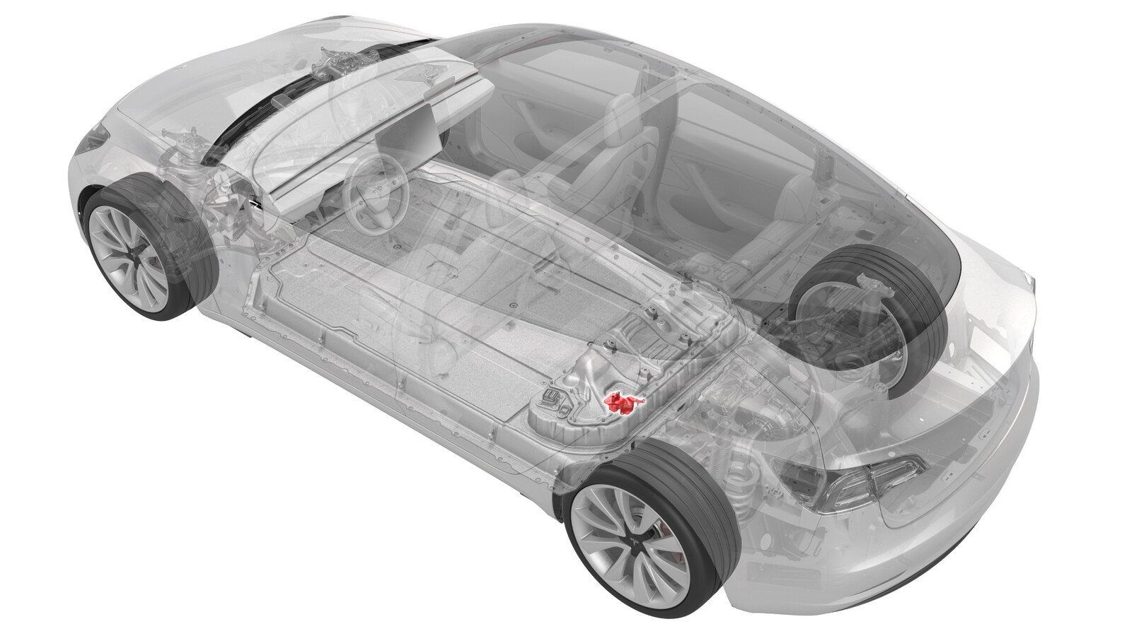
Verify that the HV battery probing cover is of the older design.
Figure 1. Older Design Figure 2. Newer Design -
Disconnect the electrical
harness from the HV battery fast charge contactor connector.
NoteSqueeze the tabs on either side of the harness connector, to release the tabs from the contactor connector.CAUTIONDo not pry the connectors apart, as this action breaks the tabs and connectors, and necessitates harness replacement.
-
Disconnect the electrical
harness from the HV battery negative contactor connectors.
-
Release the clip that
attaches the HV battery ancillary bay harness from the HV battery fast charge
contactor, and then move the harness to the left and away from the HV
battery probing cover.
-
While holding down on the HV
battery probing cover extension with one hand, pull up on the probing cover
with the other hand and fold it over the extension.
CAUTIONMake sure to wear PPE including goggles when performing this step.NoteThe folding motion should break the cover.
-
With the cover in two or more pieces, carefully remove the pieces from the
ancillary bay.
CAUTIONBe careful not to stress or damage the power cover system coolant output tube.NoteIt may be necessary to make a second break so that the larger pieces can be removed.
-
Use an ESD-safe vacuum to remove any smaller pieces and debris from the
ancillary bay.
-
If the fast charge contactor busbars have a blue choke coil, perform these
additional steps:
-
Install the newer design HV battery probing cover and verify the fit.
-
Use diagonal cutters to
remove the lip from the underside of a bolt head insulator.
-
Install the insulator over
the exposed bolt of the front drive unit positive HV joint .
- If a service procedure has requested that the HV battery probing guide be removed, remove the cover and return to that procedure. Otherwise, leave the cover in place and continue to the next step.
-
Move the HV battery ancillary bay harness to the HV battery fast charge
contactor, and then fasten the clip that attaches the harness to the
contactor.
-
Connect the electrical harness to the HV battery negative contactor
connectors.
-
Connect the electrical harness to the HV battery fast charge contactor
connector.
- Measure the voltage across the pyrotechnic battery disconnect mount points, and then install the pyrotechnic battery disconnect. See Pyrotechnic Battery Disconnect (Remove and Replace).
- Install the ancillary bay cover. See Cover - Ancillary Bay (Remove and Install).
- Connect 12V power. See 12V/LV Power (Disconnect and Connect).
- Install the rear underhood apron. See Underhood Apron - Rear (Remove and Replace).