Glove Box - Without Knee Airbags (Remove and Replace)
 Correction code
14051012
0.24
NOTE: Unless otherwise explicitly
stated in the procedure, the above correction code and FRT reflect all of the work
required to perform this procedure, including the linked procedures. Do not stack correction codes unless
explicitly told to do so.
NOTE: See Flat Rate
Times to learn more about FRTs and how they are created.
NOTE: See Personal Protection to make sure wearing proper PPE when
performing the below procedure. NOTE: See Ergonomic Precautions for safe and healthy working
practices.
Correction code
14051012
0.24
NOTE: Unless otherwise explicitly
stated in the procedure, the above correction code and FRT reflect all of the work
required to perform this procedure, including the linked procedures. Do not stack correction codes unless
explicitly told to do so.
NOTE: See Flat Rate
Times to learn more about FRTs and how they are created.
NOTE: See Personal Protection to make sure wearing proper PPE when
performing the below procedure. NOTE: See Ergonomic Precautions for safe and healthy working
practices.
- 2023-10-06: Updated USB cable disconnection step.
Remove
- Remove and secure the customer's belongings from the glove box, if needed.
- Remove the LH and RH instrument panel end caps. See End Cap - Instrument Panel - LH (Remove and Replace).
- Remove the LH and RH air wave end caps. See End Cap - Air Wave - LH (Remove and Replace).
- Remove the RH middle A-pillar trim. See Trim - A-Pillar - Middle - LH (Remove and Replace).
- Remove the RH lower A-pillar trim. See Trim - A-Pillar - Lower - LH (Remove and Replace).
- Remove the passenger footwell cover. See Cover - Footwell - Passenger (LHD) (Remove and Replace).
- Remove the main instrument panel decor trim. See Decor Trim - Instrument Panel - Main (LHD) (Remove and Replace).
- Open the glove box.
-
For HW4 vehicles, release the clip that attaches the glove box to the RH
air vent.
-
Push down on the metal
locking tab of the USB connector, and then disconnect the glove box USB
cable from the car computer.
-
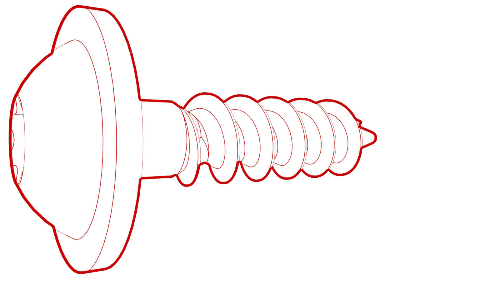
Remove the screws that attach the glove box to the IP carrier.
NoteOne screw may be inside the glove box and not visible in the following image.
-
Release the clips that attach the glove box to the IP carrier.
-
Disconnect the electrical
harness from the glove box solenoid connector, the damper connector, and the
puddle light connector.
Note2 of the electrical connectors are accessed from the bottom of the instrument panel.
-
Remove the glove box from the vehicle.
Install
-
Bring the glove box into the vehicle, and then connect the electrical harness to the glove box solenoid connector, the damper connector, and the puddle light connector.
Note2 of the electrical connectors are accessed from the bottom of the instrument panel.CAUTIONRoute the electrical harness from the puddle lamp forward of the divider at the linkages.
- Make sure that the glove box damper pin is fully seated, and not to bump the glove box damper when installing the glove box.
-
Fasten the clips that attach the glove box to the IP carrier.
-
Install the screws that attach the glove box to the IP carrier.
 2.3 Nm (1.7 lbs-ft)
 -
Connect the glove box USB
cable to the car computer.
-
For HW4 vehicles, install the clip that attaches the glove box to the RH
air vent.
- close the glove box.
- Install the main instrument panel decor trim. See Decor Trim - Instrument Panel - Main (LHD) (Remove and Replace).
- Install the passenger footwell cover. See Cover - Footwell - Passenger (LHD) (Remove and Replace).
- Install the RH lower A-pillar trim. See Trim - A-Pillar - Lower - LH (Remove and Replace).
- Install the RH middle A-pillar trim. See Trim - A-Pillar - Middle - LH (Remove and Replace).
- Install the LH and RH air wave end caps. See End Cap - Air Wave - LH (Remove and Replace).
- Install the LH and RH instrument panel end caps. See End Cap - Instrument Panel - LH (Remove and Replace).
- Verify that the glove box opens normally through the touchscreen.
- If removed earlier, put the customer's belongings back into the glove box.