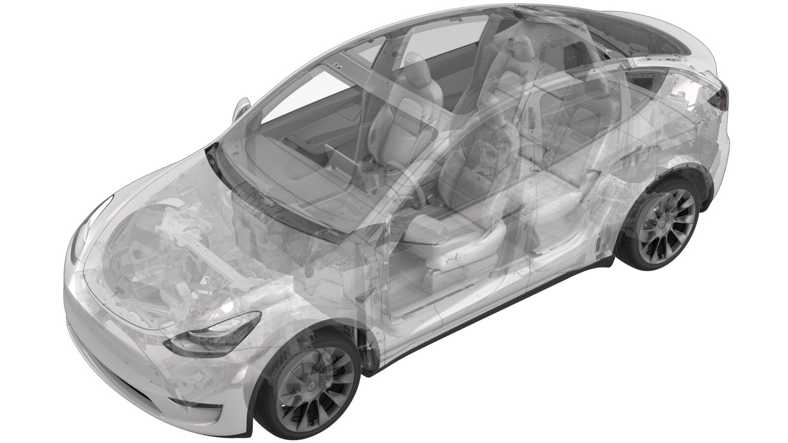
Bushing Bracket - Stabilizer Bar - Front - LH (Remove and Replace)
 Correction code
31016102
0.36
NOTE: Unless otherwise explicitly
stated in the procedure, the above correction code and FRT reflect all of the work
required to perform this procedure, including the linked procedures. Do not stack correction codes unless
explicitly told to do so.
NOTE: See Flat Rate
Times to learn more about FRTs and how they are created. To provide feedback on
FRT values, email ServiceManualFeedback@tesla.com.
NOTE: See Personal Protection to make sure wearing proper PPE when
performing the below procedure. See Ergonomic Precautions for safe and healthy working practices.
- 2025-11-10: An inflatable bag is installed between the front stabilizer bar and front valance for sufficient working space, replacing the need to fully remove the front valance.
- 2025-08-28: Added the torque table and the consumable parts information.
- 2023-06-29: Added the whole procedure video as an overview for supplemental purposes only.
Torque Specifications
| Description | Torque Value | Recommended Tools | Reuse/Replace | Notes |
|---|---|---|---|---|
| Nuts that attach the front stabilizer bar to the LH and RH front stabilizer bar links |
 98 Nm (72.3 lbs-ft) |
|
Replace | 1111543-00-A |
| Nuts that attach the front stabilizer bar to the front subframe |
 35 Nm (25.8 lbs-ft) |
|
Replace | 1111145-00-A |
Remove
- Remove the front aero shield panel. See Panel - Aero Shield - Front (Non-Structural Pack) (Remove and Replace).
-
Remove the clips that attach the front
valance to the LH wheel arch liner.
-
Remove the clips that attach the front
valance to the RH wheel liner.
-
Install an inflatable bag vertically
between the front stabilizer bar and front valance to ensure sufficient working
space.
-
Remove and discard the nut that
attaches the LH front stabilizer bar to the front stabilizer bar link, and then move the
LH front stabilizer bar link aside.
NoteUse a T40 bit to hold the stabilizer bar link ball joint in position.TIpUse of the following tool(s) is recommended:
- Torx T40 bit
- Combination Wrench 12pt 18mm
Figure 1. LH side shown, RH similar -
Remove and discard the nuts (x2) that
attach the LH front stabilizer bar to the front subframe.
TIpUse of the following tool(s) is recommended:
- 15 mm deep socket
-
Remove the bracket from the front
stabilizer bar bushing.
NoteCarefully remove the bracket with a flat head screwdriver, taking care not to damage the stabilizer bar bushing.
Install
-
Install the bracket to the front
stabilizer bar bushing.
NoteMake sure to fit the bracket onto the bushing, apply lubricant for better installation.
-
Install new nuts (x2) to attach the
stabilizer bar to the subframe, and then mark the nuts with a paint pen after they are
torqued.
 35 Nm (25.8 lbs-ft)TIpUse of the following tool(s) is recommended:
- 15 mm deep socket
-
Position the LH front stabar link
assembly to the front stabar.
NoteMay be necessary to pull down on the sway bar to allow the end link to engage.
-
Install the LH front stabilizer bar
link to the front stabilizer bar, install a new nut to attach the link to the stabilizer
bar, and then mark the nut with a paint pen after it is torqued.
 98 Nm (72.3 lbs-ft)NoteUse a T40 bit to hold the stabilizer bar link ball joint in position.TIpUse of the following tool(s) is recommended:
- Torx T40 bit
- Combination Wrench 12pt 18mm
Figure 2. LH side shown, RH similar - Remove the inflatable bag.
-
Install the clips that attach the
front valance to the LH wheel arch liner.
-
Install the clips that attach the
front valance to the RH wheel liner.
- Install the front aero shield panel. See Panel - Aero Shield - Front (Non-Structural Pack) (Remove and Replace).