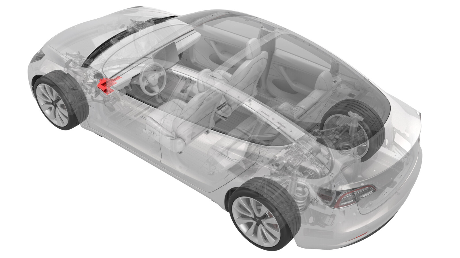
Cover - Footwell - Driver (Remove and Replace)
 Correction code
14055302
0.12
NOTE: Unless otherwise explicitly
stated in the procedure, the above correction code and FRT reflect all of the work
required to perform this procedure, including the linked procedures. Do not stack correction codes unless
explicitly told to do so.
NOTE: See Flat Rate
Times to learn more about FRTs and how they are created. To provide feedback on
FRT values, email ServiceManualFeedback@tesla.com.
NOTE: See Personal Protection to make sure wearing proper PPE when
performing the below procedure. See Ergonomic Precautions for safe and healthy working practices.
Torque Specifications
| Description | Torque Value | Recommended Tools | Reuse/Replace | Notes |
|---|---|---|---|---|
| Screw that attaches the driver footwell cover to the vehicle |
 2.5 Nm (1.8 lbs-ft) |
|
Reuse |
Remove
-
Release the clips and remove the screw that attach the driver footwell cover to the vehicle.
 2.5 Nm (1.8 lbs-ft)TIpUse of the following tool(s) is recommended:
- Torx T20 socket
- ¼ in std ratchet
- ¼ in torque wrench (installation only)
- 4 in extension
Figure 1. Left-Hand Drive (LHD) Figure 2. Right-Hand Drive (RHD) -
Disconnect the electrical connector from the puddle light, and then disconnect the diagnostic cable from the driver footwell cover.
Figure 3. LHD shown, RHD similar -
APAC vehicles only: Disconnect the OBD-II connector from the driver footwell cover.
-
Release the tabs that attach the driver footwell cover to the vehicle, and then remove the footwell cover from the vehicle.
Figure 4. LHD Figure 5. RHD Figure 6. LHD Figure 7. RHD
Install
-
Reconnect the diagnostic cable to the driver footwell cover, and then reconnect the electrical connector to the puddle light.
Figure 8. LHD shown, RHD similar -
APAC vehicles only: Reconnect the OBD-II connector to the driver footwell cover.
-
Position the footwell cover for installation by securing the front tabs to the driver knee air bag assembly, and then install the clips and the screw that attach the driver footwell cover to the vehicle.
 2.5 Nm (1.8 lbs-ft)TIpUse of the following tool(s) is recommended:
- Torx T20 socket
- ¼ in std ratchet
- ¼ in torque wrench (installation only)
- 4 in extension
Figure 9. LHD Figure 10. RHD