Hose - Return - HV Battery (Remove and Replace)
Correction code 18303702 4.08 NOTE: Unless otherwise explicitly stated in the procedure, the above correction code and FRT reflect all of the work required to perform this procedure, including the linked procedures. Do not stack correction codes unless explicitly told to do so. NOTE: See Flat Rate Times to learn more about FRTs and how they are created. To provide feedback on FRT values, email ServiceManualFeedback@tesla.com. NOTE: See Personal Protection to make sure wearing proper PPE when performing the below procedure. See Ergonomic Precautions for safe and healthy working practices.
- 2023-08-14: Updated EPB Service Mode reference.
- 2023-08-14: Added notes about vacuum refill requirement when the coolant loss is greater than 1L.
Torque Specifications
Remove
- Remove the LH lower rocker panel cover. See Cover - Rocker Panel - Lower - LH (Remove and Replace).
- Remove the LH rocker panel carrier. See Carrier - Rocker Panel - LH (Remove and Replace).
-
Remove the butyl patches
that cover the LH rocker access holes.
-
Install lift pad adapters
into the LH rocker.
WarningUse Model Y lift pad adapters (1614078-00-A) only.
- Repeat step 1 through step 4 for the RH side of the vehicle.
- Chock the LH rear wheel.
-
Open all doors and lower all
windows.
NoteLatch the rear doors to prevent accidental lockout.
- Enable the EPB Service Mode. See Parking Brake - Caliper - Rear - LH (Release)
- Remove the rear underhood apron. See Underhood Apron - Rear (Remove and Replace).
- Remove the LH middle A-pillar trim. See Trim - A-Pillar - Middle - LH (Remove and Replace).
- Remove the LH lower A-pillar trim. See Trim - A-Pillar - Lower - LH (Remove and Replace).
- Move the driver seat fully rearwards.
- Remove the driver footwell cover. See Cover - Footwell - Driver (Remove and Replace).
- Remove the LH center console side panel carpet. See Side Panel - Center Console - LH (Remove and Replace).
-
Remove the clip that
attaches the LH front carpet to the vehicle, and then fold the carpet
rearward.
-
Remove the foam plugs in the
padding underneath LH front carpet, and then remove the LH front inner HV
battery bolts (x2).
TIpUse of the following tool(s) is recommended:
- Torx Plus EP20 socket
- 6 in extension
- Raise the LH front seat fully.
- Repeat step 10 through step 17 for the RH side of the vehicle.
- Remove the 2nd row floor mat from the vehicle.
-
Lift the flap in the carpet
underneath the RH front seat, and then remove the RH middle inner HV battery
bolt that attaches the HV battery to the vehicle. Repeat this step for the
LH side of the vehicle.
TIpUse of the following tool(s) is recommended:
- 16 mm socket
- Remove the 2nd row lower seat cushion. See Seat Cushion - Lower - 2nd Row (Remove and Replace).
- Remove the LH lower C-pillar trim. See Trim - C-Pillar - Lower - LH (Remove and Replace).
-
Remove the clip securing the
LH lower B-pillar to body.
- Repeat steps 22 and 23 for the RH side of the vehicle.
-
Remove the clips (x3) that
attach the rear carpet to the vehicle.
-
Position a folded shop towel
underneath the rear cabin carpet to raise the carpet and allow access to the
rear inner HV battery bolts, and then remove the LH and RH bolts.
TIpUse of the following tool(s) is recommended:
- 16 mm socket
- 6 in extension
- Disconnect 12V power. See 12V/LV Power (Disconnect and Connect).
- Perform Vehicle HV Disablement Procedure. See Vehicle HV Disablement Procedure.
-
Disconnect the logic
electrical connector at the LH seat frame.
-
Release the clip that
attaches the logic electrical harness to the LH seat frame.
-
Remove the bolt that secures
the busbar cover access door.
TIpUse of the following tool(s) is recommended:
- 10 mm deep socket
-
Remove the bolts that attach
the charge port busbar kit to the HV header, and then lift to remove the kit
from the header.
TIpUse of the following tool(s) is recommended:
- 10 mm deep socket
-
Disconnect the HVC logic
connector, and then install the logic cap.
-
Remove and discard the nut
that attaches the DCDC ground strap to the HV battery, and then remove the
strap from the battery.
TIpUse of the following tool(s) is recommended:
- 13 mm 12-point deep socket
- 4 in extension
-
Release the positive 12V
output cover from the PCS cable, remove and discard the nut that attaches
the positive 12V output to the PCS cable, and then move the cable
aside.
TIpUse of the following tool(s) is recommended:
- 13 mm socket
- 3 in extension
-
Close all doors.
NoteDoors will be unlatched at a later step.
- Remove the wheel chocks from the wheel.
-
With assistance, push the
vehicle onto the lift, then re-chock the wheels when the vehicle is in
position.
CAUTIONOnly push the vehicle for a very short distance and at less than 1 MPH.
-
Using the lift pad adapters,
raise and support the vehicle.
WarningUse Model Y lift pad adapters (1614078-00-A) only.CAUTIONVerify jack locations prior to lifting the vehicle. Only place on lifting points at the front and rear of the rocker panels.
-
Raise and lock the vehicle
at a comfortable working height.
CAUTIONVerify that the vehicle is stable on the lift.
- Remove the front aero shield panel. See Panel - Aero Shield - Front (Non-Structural Pack) (Remove and Replace).
-
Remove the bolt and clips
that attach the LH front wheel liner to the HV battery and lower wheel well
area. Repeat this step for the RH side of the vehicle.
TIpUse of the following tool(s) is recommended:
- 10 mm socket
- 4 in extension
- Remove the front HV battery skid plate. See Skid Plate - HV Battery - Front (Remove and Replace).
-
Remove the bolt that
attaches the front drive unit HV harness to the front drive unit.
TIpUse of the following tool(s) is recommended:
- External Torx Plus EP10
-
Slide the release to unlock
the front drive unit HV connector handle of the front drive unit to HV
battery harness from the secured position.
-
Fully raise the handle on
the front drive unit HV connector.
- Remove the front drive unit HV connector from the front drive unit HV header.
-
Remove the bolt that
attaches the ground strap to the HV battery.
TIpUse of the following tool(s) is recommended:
- 10mm ratcheting combination flex head wrench
-
Release the bracket that
secures the HV connectors to the bulkhead.
-
Release the PTC HV
electrical connector from the bracket, and then disconnect the
connector.
-
Disconnect the A/C
compressor electrical connector from the HV harness.
-
Install bungee straps to
pull the LH and RH front wheel arch liners away from the HV battery and
expose the coolant hoses.
- Position a coolant drain container under the front RH corner of the HV battery.
-
Disconnect the powertrain
return hose at the RH side of the vehicle, and then plug the male and female
fittings.
-
Disconnect the rear
powertrain supply hose at the RH side of the vehicle, and then plug the male
and female fittings.
- Position the coolant drain container under the front LH corner of the HV battery.
-
Disconnect the HV battery
return hose at the LH side of the vehicle, and then plug the male and female
fittings.
-
Release the clips that
attach the battery to chiller hose to the body.
-
Disconnect the battery to
chiller hose at the LH side of the vehicle, plug the female fitting of the
hose, and allow the battery to drain.
- Remove the coolant drain container from underneath the vehicle.
- Remove the mid aero shield panel. See Panel - Aero Shield - Rear (Remove and Replace).
- Position the support stand underneath the front portion of the rear subframe.
-
Release the fir tree clips
that attach the coolant hoses to the LH shear plate.
-
Remove the smaller bolts
that attach the LH shear plate to the body.
TIpUse of the following tool(s) is recommended:
- 13 mm socket
- 3 in extension
-
Remove and discard the
larger bolt that attaches the LH shear plate and rear subframe to the body,
and then remove the LH shear plate.
TIpUse of the following tool(s) is recommended:
- 21 mm socket
- 6 in extension
-
Reinstall the larger bolt,
and hand-tighten the bolt to the rear subframe.
- Repeat steps 64 through 66 for the RH shear plate.
- Remove the support stand from underneath the rear subframe
- Remove the rear HV battery skid plate. See Skid Plate - HV Battery - Rear (Remove and Replace).
- Position the coolant drain under the rear LH side of the HV battery.
-
Release the clip and disconnect the RH inner HV battery return hose fitting
from the RH end of the HV battery platter enclosure, plug the male fitting,
and then allow the coolant to drain from the hose.
-
Release the clip and
disconnect the rear drive unit inverter inlet hose from the rear of the HV
battery, and immediately plug the male and female fittings.
- Position the coolant drain under the rear RH side of the HV battery.
-
Release the clip and
disconnect the coolant outlet hose to rear powertrain return coupling, and
immediately plug the male and female fittings.
-
Release the clip and disconnect the LH inner HV battery return hose fitting
from the LH end of the HV battery platter enclosure, plug the male fitting,
and then allow the coolant to drain from the hose.
- Remove the coolant drain from underneath the vehicle.
-
Remove the nut that attaches
the rear drive unit HV electrical harness bracket to the HV battery.
TIpUse of the following tool(s) is recommended:
- 10 mm socket
- 4 in extension
-
Slide the release to unlock
the HV battery rear drive unit connector handle of the rear drive unit to HV
battery harness from the secured position.
-
Fully raise the handle on
the HV battery rear drive unit connector.
- Remove the HV battery rear drive unit connector from the HV battery header.
-
With an assistant, put the
battery table in position, and then lower the vehicle to support the HV
battery.
NoteLine up the battery table so that the center 4 bolts of the HV battery are accessible through the opening in the battery table.
-
Remove the center bolts (x4)
that attach the HV battery through the HV battery center rail ski
cover.
TIpUse of the following tool(s) is recommended:
- External Torx Plus EP14
-
Remove the bolts (x8) that
attach the HV battery LH and RH support brackets to the vehicle.
TIpUse of the following tool(s) is recommended:
- 16 mm socket
- 3 in extension
-
Remove the bolts (x16) that
attach the HV battery to the vehicle.
NoteRecord the positions of any installed washers, as they will be reinstalled to the same locations during the installation procedure.TIpUse of the following tool(s) is recommended:
- 13 mm socket
- 3 in extension
- With an assistant, raise the vehicle and remove the HV battery from underneath the vehicle.
-
Remove and discard the
ancillary bay perimeter seal from the HV battery.
-
Release the clips that attach the RH inner HV battery return hose to the HV
battery.
-
Release the clips (x5) that attach the HV battery return hose to the LH
side of the HV battery, and remove the hose from the HV battery.
Install
-
Position the HV battery return hose onto the LH side of the HV battery, and
then install the clips (x5) that attach the hose to the HV battery.
-
Install the clips that attach the RH inner HV battery return hose to the HV
battery.
-
Install a new ancillary bay
perimeter seal onto the HV battery.
-
Install and hand-tighten the
adjustable elements (x4) on the ancillary bay cover counter-clockwise so
that they are fully engaged.
CAUTIONHand-tighten only.
- Install the HV battery alignment rods; 2 at the front of the vehicle and 2 at the HV battery near the ancillary bay.
- With an assistant, position the HV battery underneath the vehicle.
-
Lower the vehicle to the HV
battery, and with an assistant, align the holes with the alignment rods.
NoteDo not fully lower the vehicle onto the HV battery. The battery will still need to slightly move to install the bolts in the following steps.CAUTIONMake sure that the coolant hoses and HV harnesses are not caught on the alignment rods or sandwiched between the HV battery and the vehicle.
-
Install and hand-tighten the
smaller bolts that would attach the LH and RH shear plates to the
body.
NoteDo not install the shear plates at this time.
Figure 1. LH shown, RH similar -
Install and hand-tighten the
LH and RH bolts (x16) that attach the HV battery to the body.
NoteInstall the washers to the locations recorded earlier during removal.
- Remove HV battery front alignment rods.
-
Install and hand-tighten the
bolts (x8) that attach the HV battery LH and RH support brackets to the
vehicle.
-
Install and hand-tighten the
bolts (x4) that attach the center portion of the HV battery through the HV
battery center rail ski cover.
- Open the LH rear door
- Remove the HV battery alignment rod from the LH rear inner bolt location.
-
Install and hand-tighten the
LH rear inner HV battery bolts.
-
Lift the carpet flap, and
then install and hand-tighten the LH middle inner HV battery bolt.
- Close the LH rear door.
- Open the LH front door.
-
Install and hand-tighten
both LH front inner HV battery bolts.
- Close the LH front door.
- Repeat step 13 through step 20for the RH side of the vehicle.
- Fully lower the vehicle onto the HV battery.
-
Torque the LH and RH bolts
(x16) that attach the HV battery to the vehicle.
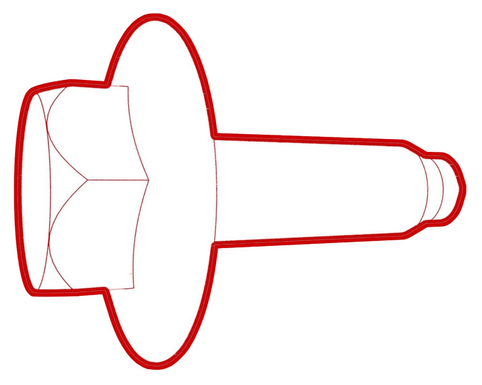 35 Nm (25.8 lbs-ft)TIpUse of the following tool(s) is recommended:
- 13 mm socket
- 3 in extension
-
Torque the bolts (x8) that
attach the HV battery LH and RH support brackets to the vehicle.
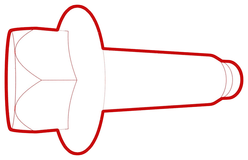 110 Nm (81.1 lbs-ft)TIpUse of the following tool(s) is recommended:
- 16 mm socket
- 3 in extension
-
Torque the bolts (x4) that
attach the center portion of the HV battery through the center ski
cover.
 35 Nm (25.8 lbs-ft)TIpUse of the following tool(s) is recommended:
- External Torx Plus EP14
- With an assistant, raise the vehicle, and then remove the battery table from underneath the vehicle.
- Set the vehicle to a comfortable working height, and then lower the vehicle into locks.
- Position the support stand to support the front portion of the rear subframe.
-
Remove the smaller bolts
(x2) and the larger bolt that attach the LH shear plate to the
vehicle.
Figure 2. LH shown, RH similar -
Install the LH shear plate,
and then install and hand-tighten the larger bolt that attaches the shear
plate to the vehicle.
-
Install and hand-tighten the
smaller bolts (x2) that attach the shear plate to the HV battery.
Figure 3. LH shown, RH similar -
Torque the large bolt that
attaches the LH shear plate to the body.
 130 Nm (95.9 lbs-ft)TIpUse of the following tool(s) is recommended:
- 21 mm socket
- 6 in extension
-
Torque the small bolts that
attach the LH shear plate to the body.
 35 Nm (25.8 lbs-ft)TIpUse of the following tool(s) is recommended:
- 13 mm socket
- 3 in extension
- Repeat step 29 through step 33 for the RH shear plate.
- Remove the support stand from underneath the rear subframe
-
Fasten the fir tree clips
that attach the coolant hoses to the LH and RH shear plates.
Figure 4. LH shown, RH similar -
Fully raise the handle on
the HV battery rear drive unit connector of the rear drive unit to HV
battery harness.
-
Install the HV connector
special tool onto the HV battery rear drive unit connector.
-
Use both hands to firmly
connect the HV battery rear drive unit connector of the rear drive unit to
HV battery harness to the HV battery header.
CAUTIONMake sure that the connector fits the header squarely and tightly, and that both retention pins enter the handle.
- Remove the HV connector special tool from the HV battery rear drive unit connector.
-
While pressing the HV
battery rear drive unit connector onto the HV battery header, fully lower
the handle.
CAUTIONMake sure that the handle does not bind as it is lowered.
-
Slide the release to lock
the HV battery rear drive unit connector handle in the secured
position.
-
Verify that the HV battery
rear drive unit connector is fully seated, and compare both sides of the
connector that it is properly secured in place.
NoteAn improperly seated connector might lead to connector damage and rear drive unit problems later on.
-
Install the nut that
attaches the rear drive unit HV electrical harness bracket to the HV
battery.
 10 Nm (7.4 lbs-ft)TIpUse of the following tool(s) is recommended:
- 10 mm socket
- 4 in extension
- Position the coolant drain beneath the RH rear of the HV battery.
-
Remove the hose plugs, and
then connect coolant outlet hose to rear power train return hose.
CAUTIONPerform a push-pull test to verify that the hose is fully seated.
Coolant loss greater than 1L requires vacuum fill.
-
Remove the hose plug, and then connect the RH inner HV battery return hose
fitting to the RH end of the HV battery platter enclosure.
CAUTIONPerform a push-pull test to verify that the hose is fully seated.
- Position the coolant drain underneath the LH rear of the HV battery.
-
Remove the hose plugs, and
then connect rear drive unit inverter inlet hose to the rear of HV
battery.
CAUTIONPerform a push-pull test to verify that the hose is fully seated.
Coolant loss greater than 1L requires vacuum fill.
-
Remove the plug, and then connect the LH inner HV battery return hose
fitting to the LH end of the HV battery platter enclosure.
CAUTIONPerform a push-pull test to verify that the hose is fully seated.
Coolant loss greater than 1L requires vacuum fill.
- Remove the coolant drain container from underneath the vehicle.
- Install the rear HV battery skid plate, but only hand-tighten the fasteners. See Skid Plate - HV Battery - Rear (Remove and Replace).
- Torque the fasteners that attach the rear skid plate to the vehicle. See Skid Plate - HV Battery - Rear (Remove and Replace).
- Install the mid aero shield panel. See Panel - Aero Shield - Rear (Remove and Replace).
- Position the coolant drain container under the front LH side of the HV battery.
-
Remove the plugs from the HV
battery return hose at the LH side of the vehicle, immediately connect the
male and female fittings, and then fasten the clip.
NotePerform a push-pull-push test on the fittings to make sure that they are secure.
- Position the coolant drain container under the HV battery front manifold coolant hose.
-
Remove the plugs from the
chiller to HV battery hose and the manifold at the LH side of the vehicle,
immediately connect the male and female fittings, and then fasten the
clip.
NotePerform a push-pull-push test on the fittings to make sure that they are secure. Coolant loss greater than 1L requires vacuum fill.
-
Fasten the clips that attach
the HV battery front manifold hose to the body.
- Position the coolant drain container under the front RH side of the HV battery.
-
Remove the plugs from the
rear powertrain supply hose at the RH side of the vehicle, immediately
connect the male and female fittings, and then fasten the clip.
NotePerform a push-pull-push test on the fittings to make sure that they are secure. Coolant loss greater than 1L requires vacuum fill.
-
Remove the plugs from the
powertrain return hose at the RH side of the vehicle, immediately connect
the male and female fittings, and then fasten the clip.
NotePerform a push-pull-push test on the fittings to make sure that they are secure. Coolant loss greater than 1L requires vacuum fill.
- Remove the coolant drain from underneath the vehicle.
- Remove the plastic bracket that attaches the HV connectors to the HV battery.
-
Connect the A/C HV
connector, and then engage the connector lock.
-
Connect the PTC HV
electrical connector, and then engage the connector lock.
-
Install the bolt that
attaches the ground strap to the HV battery
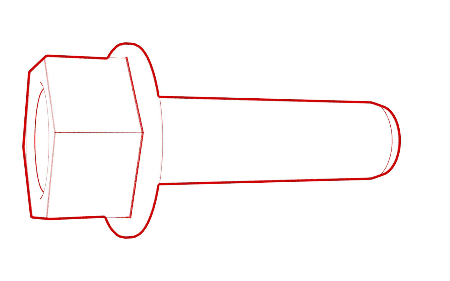 10 Nm (7.4 lbs-ft)TIpUse of the following tool(s) is recommended:
- 10mm ratcheting combination flex head wrench
-
Fully raise the handle on
the front drive unit HV connector of the front drive unit to HV battery
harness.
-
Install the HV connector
special tool onto the front drive unit HV connector.
-
Use both hands to firmly
connect the front drive unit HV connector of the front drive unit to HV
battery harness to the front drive unit HV header.
CAUTIONMake sure that the connector fits the header squarely and tightly, and that both retention pins enter the handle.
- Remove the HV connector special tool from the front drive unit HV connector.
-
While pressing the front
drive unit HV connector onto the front drive unit HV header, fully lower the
handle.
CAUTIONMake sure that the handle does not bind as it is lowered.
-
Slide the release to lock
the front drive unit HV connector handle in the secured position.
-
Verify that the front drive
unit HV connector is fully seated, and compare both sides of the connector
that it is properly secured in place.
NoteAn improperly seated connector might lead to connector damage and front drive unit problems later on.
-
Install the bolt that
attaches the front drive unit HV harness to the front drive unit.
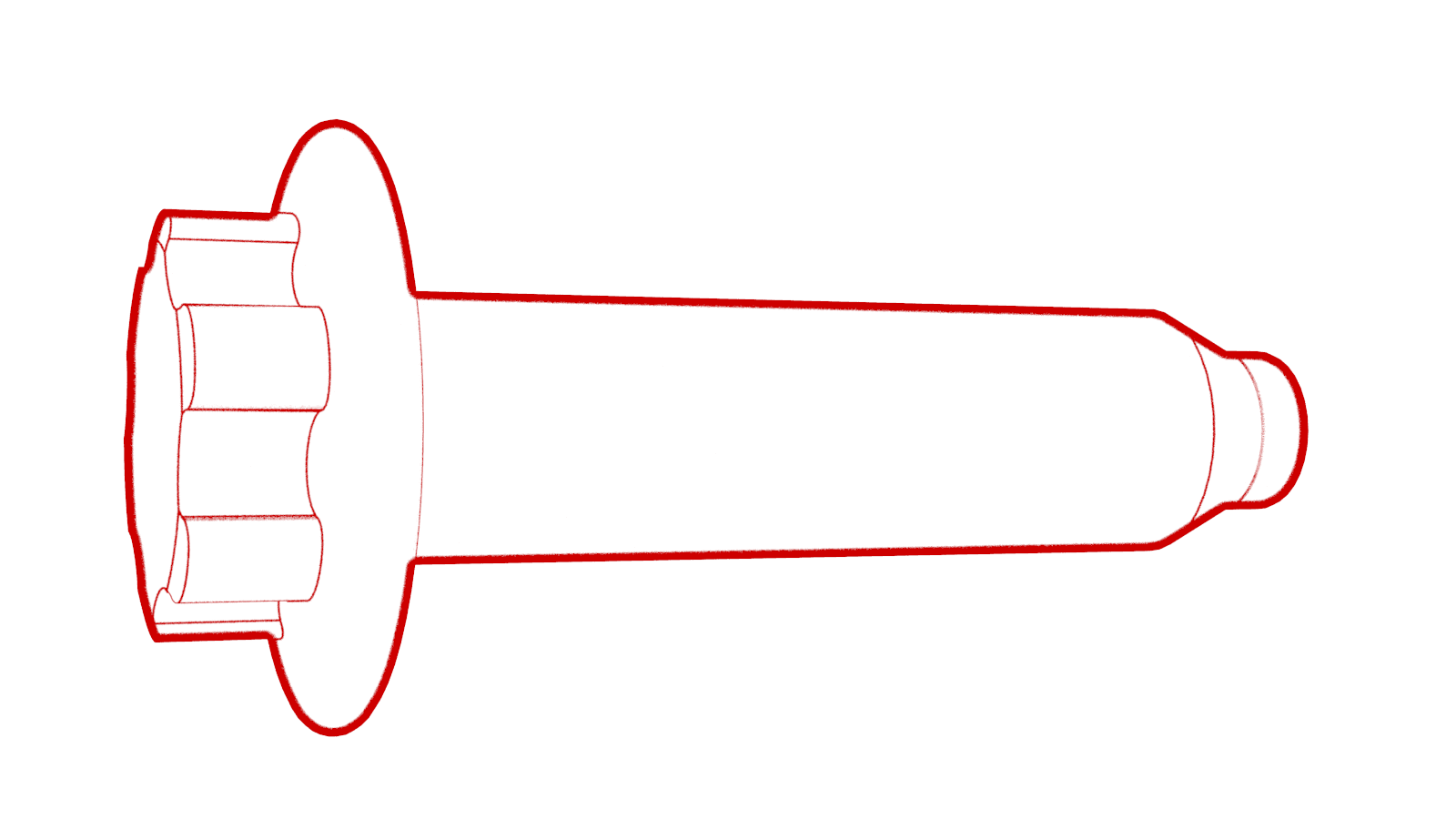 10 Nm (7.4 lbs-ft)TIp
- External Torx Plus EP10
- Install the front HV battery skid plate. See Skid Plate - HV Battery - Front (Remove and Replace).
- Remove the bungee straps from the LH and RH wheel arch liners.
-
Install the bolt and clips
that attach the LH front wheel liner to the HV battery and lower wheel well
area. Repeat this step for the RH side of the vehicle.
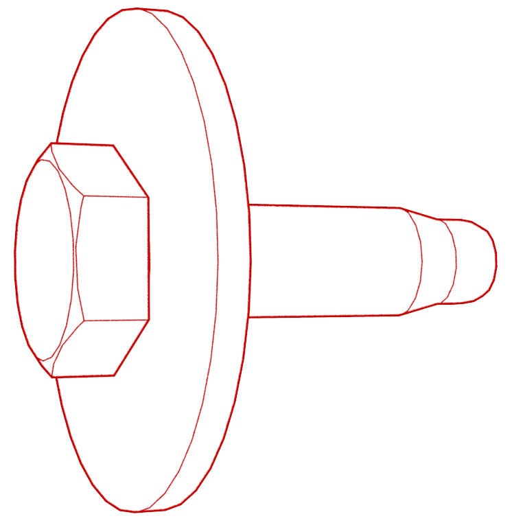 5 Nm (3.7 lbs-ft)TIpUse of the following tool(s) is recommended:
- 10 mm socket
- 4 in extension
- Install the front aero shield panel. See Panel - Aero Shield - Front (Non-Structural Pack) (Remove and Replace).
- Lower the vehicle fully, and chock a wheel.
-
Remove the chock, and with
an assistant, push the vehicle away from the lift to a stall, and then
re-chock the wheel.
CAUTIONPush the vehicle for a very short distance and at less than 1 MPH.
-
Install the nut that
attaches the positive 12V output to the PCS cable, and then close the
cover.
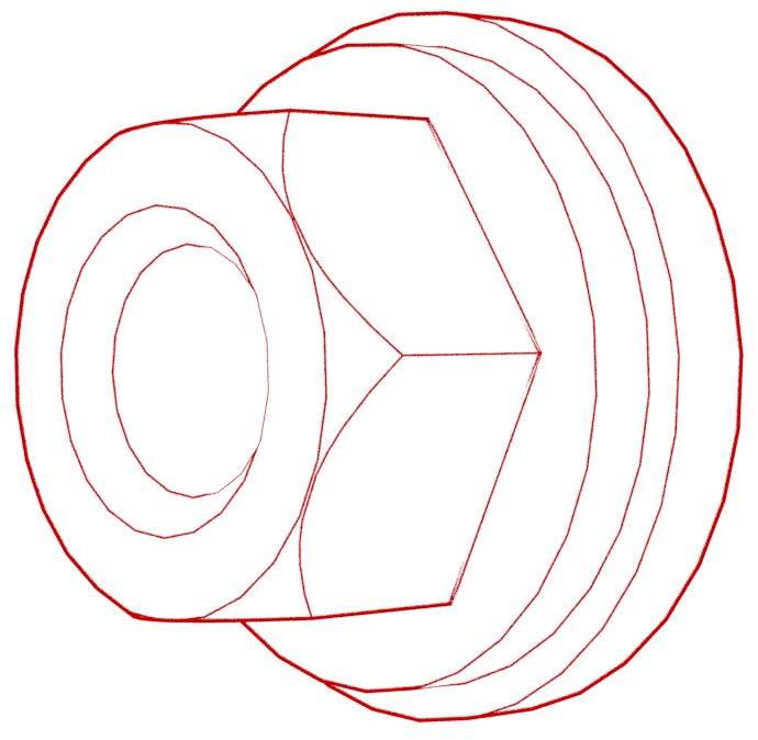 15 Nm (11.1 lbs-ft)CAUTIONEnsure the rubber boot is not pinched between the cable terminal and pass through.TIpUse of the following tool(s) is recommended:
- 13 mm socket
- 3 in extension
-
Install a new nut that
attaches the DCDC ground strap to the HV battery.
 15 Nm (11.1 lbs-ft)TIpUse of the following tool(s) is recommended:
- 13 mm 12-point deep socket
- 4 in extension
-
Remove the logic cap, and
then connect the HVC logic connector.
- Clean the busbar HV connector contact surface with an IPA wipe, and allow to dry for 1 minute.
- Clean the HV connector contact surface with an IPA wipe, and allow to dry for 1 minute.
- Apply one drop of electrical joint compound on each of the HV connector joints.
- Position the busbar kit connector and lower onto the HV header.
-
Install the bolts that
attach the charge port busbar kit to the HV header.
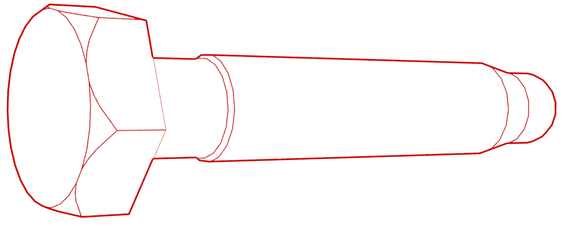 9 Nm (6.6 lbs-ft)TIpUse of the following tool(s) is recommended:
- 10 mm deep socket
- Perform a zero adjust of the Hioki resistance meter in preparation to measure resistances. See Resistance Meter (Zero Adjust).
- Put on HV insulating gloves and leather over gloves.
-
At the ancillary bay, use the
Hioki resistance meter to measure the resistance between the charge port
busbar lead and the ancillary bay HV header bolt head. Also perform this test on
the other lead and bolt head.
NoteThe acceptable resistance is between 0.050 mΩ (50 μΩ) and 0.195 mΩ (195 μΩ). If the measured resistance is above 0.195 mΩ (195 μΩ), there is too much resistance in the High Voltage joint. Remove the fastener, clean areas with isopropyl alcohol, install fastener back and test again, as appropriate.NoteIf the resistance is lower than 0.050 mΩ (50 μΩ), reposition the probes and measure again. If after 4 attempts the resistance is consistently lower than 0.050 mΩ (50 μΩ), the test has passed; continue to the next step.
- Remove the HV insulating gloves and leather over gloves.
-
Install the bolt that
secures the busbar cover access door.
 9 Nm (6.6 lbs-ft)TIpUse of the following tool(s) is recommended:
- 10 mm deep socket
-
Connect the logic connector
at the LH seat frame.
-
Install the clip that
attaches the logic electrical harness to the LH seat frame.
-
Torque the LH and RH rear
inner HV battery bolts.
 66 Nm (48.7 lbs-ft)TIpUse of the following tool(s) is recommended:
- 16 mm socket
- 6 in extension
- Remove the folded shop towel from underneath the rear cabin carpet.
-
Install the clips (x3) that
attach the rear carpet to the vehicle.
-
Install the clip securing
the LH lower B-pillar to body.
- Install the LH lower C-pillar trim. See Trim - C-Pillar - Lower - LH (Remove and Replace).
- Repeat steps 100 and 101 for the RH side of the vehicle.
- Install the 2nd row lower seat cushion. See Seat Cushion - Lower - 2nd Row (Remove and Replace).
-
Torque the LH middle inner
HV battery bolt, and then fold the carpet to its original position. Repeat
this step on the RH side of the vehicle.
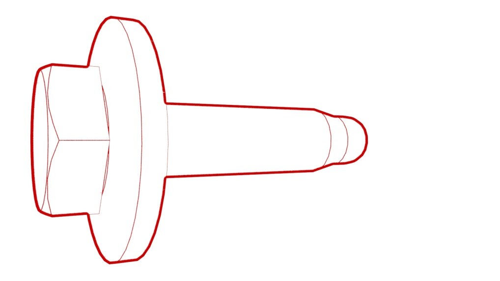 66 Nm (48.7 lbs-ft)TIpUse of the following tool(s) is recommended:
- 16 mm socket
- Install the 2nd row floor mat into the vehicle.
-
Torque both RH front inner
HV battery bolts, and then install the foam plugs.
 136 Nm (100.3 lbs-ft)TIpUse of the following tool(s) is recommended:
- Torx Plus EP20 socket
- 6 in extension
-
Fold the RH front main cabin
carpet forward to its original position, and then install the clip that
attaches the LH carpet to the vehicle.
- Install the RH lower A-pillar trim. See Trim - A-Pillar - Lower - LH (Remove and Replace).
- Install the RH middle A-pillar trim. See Trim - A-Pillar - Middle - LH (Remove and Replace).
- Install the RH center console side panel carpet. See Side Panel - Center Console - LH (Remove and Replace).
- Install the RH front floor mat.
- Install the front passenger footwell cover. See Cover - Footwell - Driver (Remove and Replace).
- Repeat step 106 through step 112 for the LH side of the vehicle.
-
Remove the coolant bottle
cap, inspect the coolant level, and top off coolant as necessary.
NoteEnsure that the fluid level is at the Max line.
- Connect 12V power. See 12V/LV Power (Disconnect and Connect).
- On the vehicle touchscreen, press and hold the park button to release EPB service mode.
-
Perform the following
routine using Service Mode or Toolbox (see 0005 - Service Modes):
TEST_VCFRONT_X_THERMAL-COOLANT-AIR-PURGEvia Toolbox: (link)via Service Mode:
- Thermal ➜ Actions ➜ Coolant Purge Stop or Coolant Purge Start
- Thermal ➜ Coolant System ➜ Coolant Purge Start
- Drive Inverter ➜ Front Drive Inverter Replacement ➜ Coolant Air Purge
- Drive Inverter ➜ Rear Drive Inverter Replacement ➜ Coolant Air Purge
- Drive Inverter ➜ Rear Left Drive Inverter Replacement ➜ Coolant Air Purge
- Drive Inverter ➜ Rear Right Drive Inverter Replacement ➜ Coolant Air Purge
- Drive Unit ➜ Front Drive Unit Replacement ➜ Coolant Air Purge
- Drive Unit ➜ Rear Drive Unit Replacement ➜ Coolant Air Purge
NoteAllow the routine to complete, and then click the "x" at the top right of the window to close. - Inspect the coolant level and top off coolant as necessary.
- Install coolant bottle cap.
-
Perform the following
routine using Service Mode or Toolbox (see 0005 - Service Modes):
TEST-SELF_VCFRONT_X_THERMAL-PERFORMANCEvia Toolbox: (link)via Service Mode: Thermal ➜ Actions ➜ Test Thermal Performancevia Service Mode Plus:
- Drive Inverter ➜ Front Drive Inverter Replacement ➜ Thermal System Test
- Drive Inverter ➜ Rear Drive Inverter Replacement ➜ Thermal System Test
- Drive Inverter ➜ Rear Left Drive Inverter Replacement ➜ Thermal System Test
- Drive Inverter ➜ Rear Right Drive Inverter Replacement ➜ Thermal System Test
- Drive Unit ➜ Front Drive Unit Replacement ➜ Thermal System Test
- Drive Unit ➜ Rear Drive Unit Replacement ➜ Thermal System Test
NoteAllow the routine to complete, and then click the "x" at the top right of the window to close. - Install the rear underhood apron. See Underhood Apron - Rear (Remove and Replace).
- Raise all windows and close all doors.
-
Remove lift pads from the LH
rocker.
-
Install the butyl patch that
covers the LH rocker access holes.
- Install the LH rocker panel carrier. See Carrier - Rocker Panel - LH (Remove and Replace).
- Install the LH lower rocker panel cover. See Cover - Rocker Panel - Lower - LH (Remove and Replace).
- Repeat step 123 though step 126 for the RH side of the vehicle.