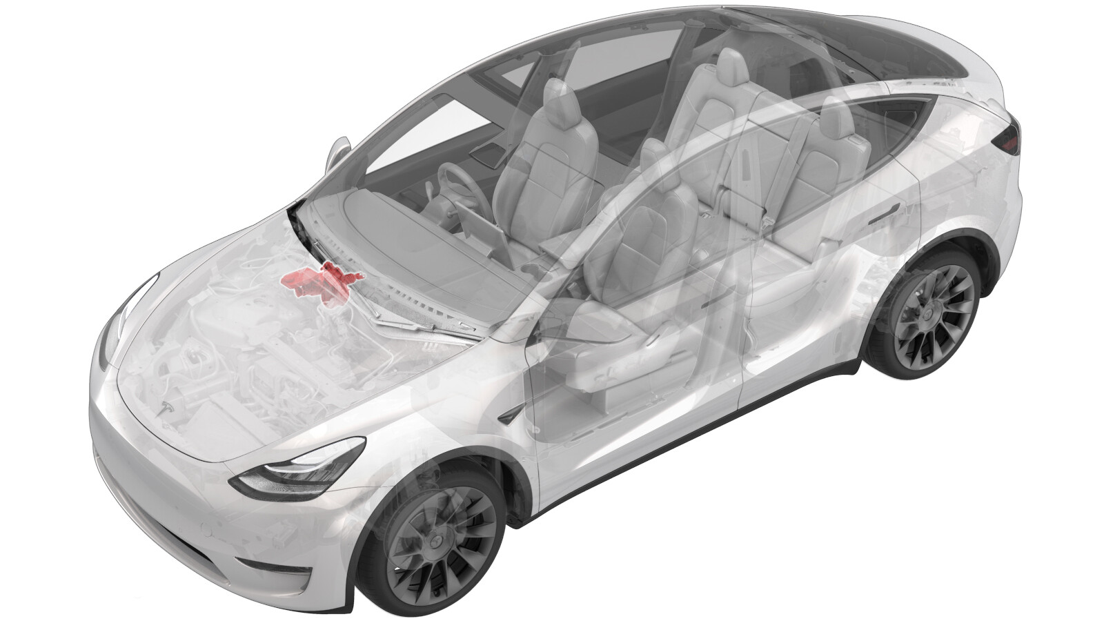
Electromechanical Brake Booster Assembly (Non-Structural Pack) (RHD) (Remove and Replace)
 Correction code
33201102
1.68
NOTE: Unless otherwise explicitly
stated in the procedure, the above correction code and FRT reflect all of the work
required to perform this procedure, including the linked procedures. Do not stack correction codes unless
explicitly told to do so.
NOTE: See Flat Rate
Times to learn more about FRTs and how they are created.
NOTE: See Personal Protection to make sure wearing proper PPE when
performing the below procedure. NOTE: See Ergonomic Precautions for safe and healthy working
practices.
Correction code
33201102
1.68
NOTE: Unless otherwise explicitly
stated in the procedure, the above correction code and FRT reflect all of the work
required to perform this procedure, including the linked procedures. Do not stack correction codes unless
explicitly told to do so.
NOTE: See Flat Rate
Times to learn more about FRTs and how they are created.
NOTE: See Personal Protection to make sure wearing proper PPE when
performing the below procedure. NOTE: See Ergonomic Precautions for safe and healthy working
practices.
- 2025-06-26: Modified brake bleeding method to bleed through inner valves only.
Remove
- Open the RH front door and lower the RH front window.
- Move the driver seat fully rearward.
- Raise and support the vehicle. See Raise Vehicle - 2 Post Lift.
- Remove the underhood storage unit. See Underhood Storage Unit (Remove and Replace).
- Disconnect 12V power. See 12V/LV Power (Disconnect and Connect).
- Remove the 12V battery. See 12V/LV Battery (Remove and Replace).
- Remove the LH and RH wiper arms. See Wiper Arms (Remove and Replace).
- Remove the cowl screen panel. See Panel - Cowl Screen (Remove and Replace).
- Remove the wiper module. See Wiper Module (Remove and Replace).
-
Remove the bolt that attaches the
fresh air intake duct to the strut tower brace.
-
Release the fresh intake duct from the
studs (x2) on the bulkhead, and then remove the duct from the vehicle.
-
Release the locking tab, and then
disconnect the brake fluid reservoir electrical connector.
CAUTIONDO NOT push down on the red locking tab. Pull the tab away from the connector until the connector is unlocked, and then continue pulling the main body of the connector to fully disconnect it.
-
Release the locking tab, and then
disconnect the harness connectors (x2) from the brake booster assembly.
CAUTIONDO NOT push down on the red locking tab. Pull the tab away from the connector until the connector is unlocked, and then continue pulling the main body of the connector to fully disconnect it.
- Place an absorbent material beneath the brake booster and reservoir area.
- Using a brake fluid syringe, remove the brake fluid from the reservoir.
-
Disconnect the brake lines (x2) from
the master cylinder.
TIpUse of the following tool(s) is recommended:
- 12 mm 12pt combination wrench
- 12 mm flare nut crowfoot socket
- Remove the driver's footwell. See Cover - Footwell - Driver (Remove and Replace).
-
Remove the cotter clip from the clevis
pin on the brake pedal assembly, and then remove the clevis pin.
-
Remove and discard the nuts that
attach the brake booster to the bulkhead, and then remove the brake booster assembly
from the vehicle.
TIpUse of the following tool(s) is recommended:
- 13 mm deep socket
- 6 in extension
Install
Installation procedure is the reverse of removal, except for the following:
-
Install new nuts that attach the brake booster to the bulkhead.
 16.5 Nm (12.2 lbs-ft)
 - Redeploy the firmware. See Software Reinstall - Toolbox.
-
Bleed the LH and RH front brake
calipers through the brake calipers' inner bleed valves until clean fluid without air bubbles flows out of the
caliper.
NoteIt is not necessary to bleed the brake calipers through the outer bleed valves.
- Flush the LH front caliper using the inner bleed valve until a noticeable reduction in air bubbles is observed.
- Flush the RH front caliper using the inner bleed valve until a noticeable reduction in air bubbles is observed.
- Bleed the LH front caliper using the inner bleed valve. See Brake Fluid Bleed/Flush for details.
- Bleed the RH front caliper using the inner bleed valve. See Brake Fluid Bleed/Flush for details.
- Make sure to perform the brake stiffness test. See Brake Fluid Bleed/Flush for details.