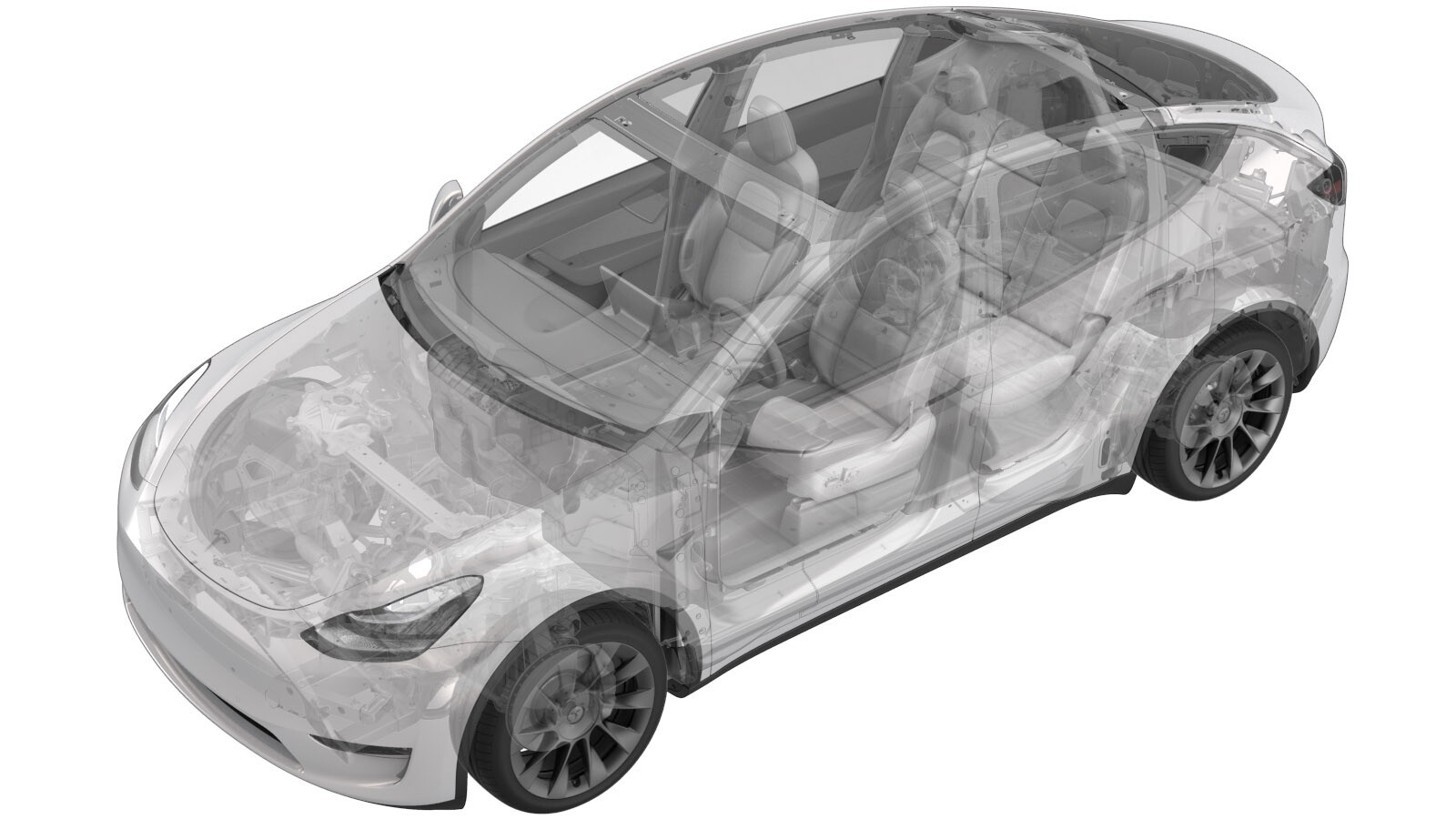
Crush Can - Upper - Front - LH (Remove and Replace)
 Correction code
10012402
1.38
NOTE: Unless otherwise explicitly
stated in the procedure, the above correction code and FRT reflect all of the work
required to perform this procedure, including the linked procedures. Do not stack correction codes unless
explicitly told to do so.
NOTE: See Flat Rate
Times to learn more about FRTs and how they are created. To provide feedback on
FRT values, email ServiceManualFeedback@tesla.com.
NOTE: See Personal Protection to make sure wearing proper PPE when
performing the below procedure. See Ergonomic Precautions for safe and healthy working practices.
- 2023-06-16: Updated torque for the fastener that attaches the crush can to the fender support.
Remove
- Open the LH front door and lower the LH front window.
- Raise and support the vehicle. See Raise Vehicle - 2 Post Lift.
- Remove the underhood storage unit. See Underhood Storage Unit (Remove and Replace).
- Disconnect 12V power. See 12V/LV Power (Disconnect and Connect).
-
Remove the bolts that attach the top
of the front fascia to the vehicle.
 4 Nm (2.9 lbs-ft)TIpUse of the following tool(s) is recommended:
- 10 mm socket
- ¼ in std ratchet
- 2 in extension
-
Wurth ¼ in hexagon 1 Nm - 5
Nm torque wrench (installation only)
- ¼ in hex to ¼ in square 2 in adapter
-
Remove the coolant bottle cap.
-
Release the connector lock, and then
disconnect the active grille shutter electrical connector.
CAUTIONDo not push down on the red tab. Pull the red tab to release the connector lock.
-
Remove the ambient temperature sensor
cover from the active grille shutter, and then disconnect the sensor electrical
connector.
-
Remove the bolts that attach the
underhood storage unit reinforcement bracket to the cooling fan, and then slide the
bracket rearward for clearance.
TIpUse of the following tool(s) is recommended:
- External Torx Plus EP14
- Flex head ratchet/flex head torque wrench
- 3 in extension
- Remove the front wheels. See Wheel Assembly (Remove and Install).
- Remove the front aero shield panel. See Panel - Aero Shield - Front (Non-Structural Pack) (Remove and Replace).
- Remove the LH front fender garnish. See Garnish - Fender - Front - LH (Remove and Replace)
-
Release the clips (x4) that attach the
front portion of the LH front wheel arch liners to the vehicle, and then move the wheel
arch liner aside to perform the following steps.
Figure 1. LH shown; RH similar -
Remove the bolt that attaches the LH
corner of the front fascia to the fender.
 4 Nm (2.9 lbs-ft)TIpUse of the following tool(s) is recommended:
- 10 mm socket
- ¼ in std ratchet
-
Wurth ¼ in hexagon 1 Nm - 5
Nm torque wrench (installation only)
- ¼ in hex to ¼ in square 2 in adapter
Figure 2. LH shown; RH similar - Remove the RH front fender garnish. See Garnish - Fender - Front - LH (Remove and Replace)
-
Remove the clips (x6) that attach the
RH front wheel liner to the front fascia.
-
Remove the bolt that attaches the RH corner of the front fascia to the fender.
 4 Nm (2.9 lbs-ft)TIpUse of the following tool(s) is recommended:
- 10 mm socket
- ¼ in std ratchet
-
Wurth ¼ in hexagon 1 Nm - 5
Nm torque wrench (installation only)
- ¼ in hex to ¼ in square 2 in adapter
Figure 3. LH shown; RH similar -
Release the connector lock, and then
disconnect the electrical connector from the front fascia in the RH wheel well.
-
If present, release the clip that
attaches the electrical harness to the pedestrian warning speaker assembly.
-
If present, slide the locking tab away
from the connector, and then press down on the locking tab to disconnect the connector
from the pedestrian warning speaker assembly.
-
With an assistant, release the LH and
RH sides of the front fascia, and then carefully pull the fascia up and forward to
remove it from the vehicle. Place the fascia on a padded surface.
CAUTIONCarefully release the tabs that attach the lower headlight bracket to the front fascia, otherwise the tabs can be broken.
Figure 4. LH shown; RH similar WarningThe corners of the ankle catcher are very sharp and might cause personal injury.LH ankle catcher corner shown; RH corner similar
- Raise the vehicle fully and lower lift onto locks.
- Place a coolant drain container below the LH front of the vehicle.
-
Release the clip that attaches the
radiator inlet hose to the cooling fan module, disconnect the hose, allow the coolant to
drain, and then plug the male and female fittings.
- Place the coolant drain container below the RH front of the vehicle.
-
Release the clip that attaches the
radiator outlet hose from the cooling fan module, disconnect the hose, allow the coolant
to drain, and then plug the male and female fittings.
-
Disconnect the electrical harness from
the cooling fan module connector.
-
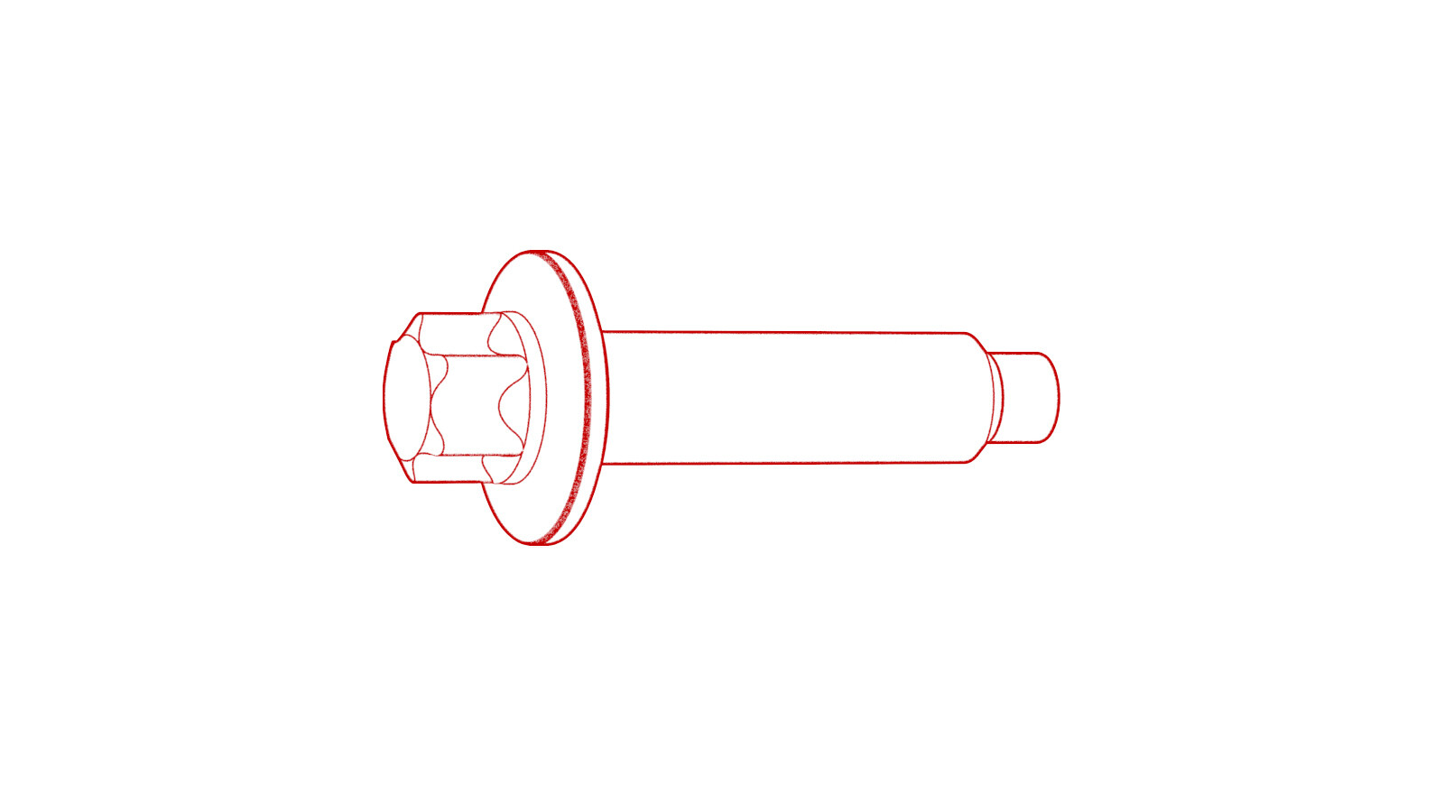
Remove the bolts that attach the lower
LH and RH of the cooling fan module to the ankle catcher.
NoteWith assistance, lift up on the cooling fan module to ease the removal of the bolts.TIpUse of the following tool(s) is recommended:
- 8 mm socket
- Flex head ratchet/flex head torque wrench
- 4 in extension
Figure 5. LH Side Figure 6. RH Side -
Remove the cooling fan module assembly
from the vehicle.
-
Remove the front bumper beam. See
Bumper Beam - Front (Remove and Replace).
NoteIt is not necessary to remove the LH and RH front bumper crash accelerometer sensors or the foam from the bumper beam assembly after removing the assembly from the vehicle.
-
Release the clip from the LH crush
can.
-
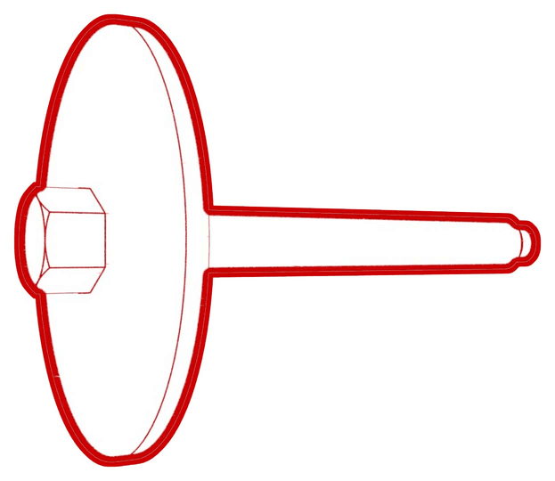
Remove the bolt that attaches the LH
front upper crush can to the vehicle.
 30 Nm (22.1 lbs-ft)TIpUse of the following tool(s) is recommended:
- 13 mm socket
-
Remove and discard the bolts (x4) that
attach the LH front upper crush can to the vehicle, and then remove the crush can from
the vehicle.
 90 Nm (66.4 lbs-ft)TIpUse of the following tool(s) is recommended:
- 18 mm socket
Install
-
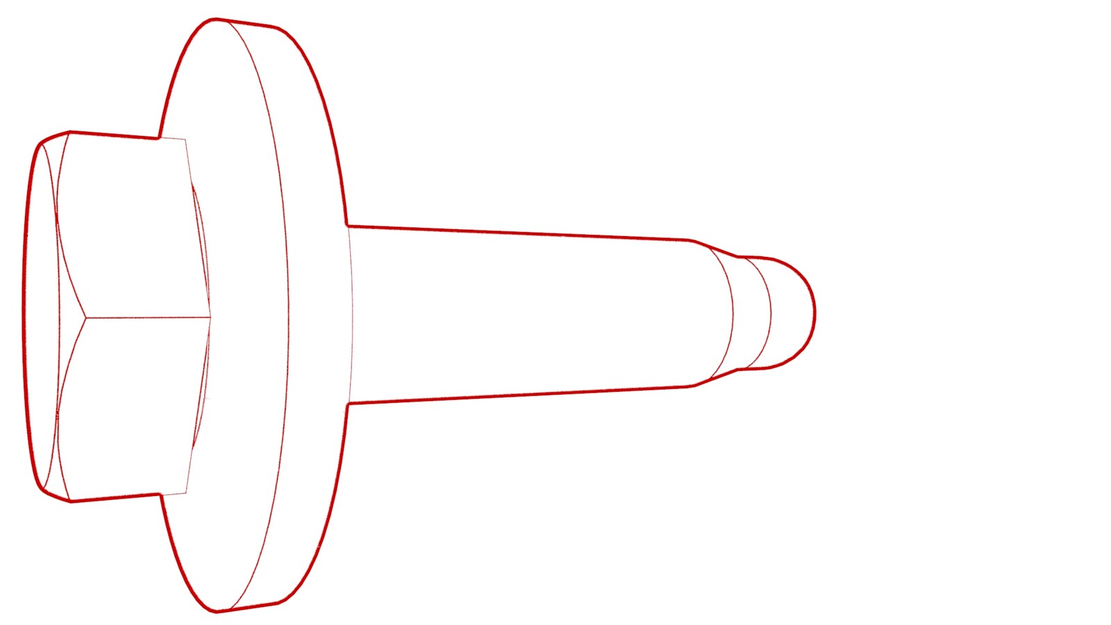
Position the LH front upper crush can
into the vehicle, and then install new bolts (1120775-00-A) (x4) that attach the crush
can to the vehicle.
 90 Nm (66.4 lbs-ft)TIpUse of the following tool(s) is recommended:
- 18 mm socket
-
Install the bolt that attaches the LH
front upper crush can to the vehicle.
 30 Nm (22.1 lbs-ft)TIpUse of the following tool(s) is recommended:
- 13 mm socket
-
Install the clip from the LH crush
can.
-
Use a dead blow hammer to install the
front bumper beam to the LH and RH crush cans.
-
Install the new bolts that attach the
LH and RH sides of the front bumper beam to the LH and RH crush cans.
 75 Nm (55.3 lbs-ft)TIpUse of the following tool(s) is recommended:
- 15 mm socket
- 3 in extension
-
Install the bolts that attach the LH
and RH sides of the front bumper beam to the ankle catcher.
 16 Nm (11.8 lbs-ft)TIpUse of the following tool(s) is recommended:
- 13 mm socket
- 3 in extension
-
Connect the electrical connectors to
the LH and RH front bumper crash accelerometer sensors.
- Raise the vehicle fully and lower lift onto locks.
- With assistance, position the cooling fan module assembly into the vehicle, and then loosely install the bolts that attach the module assembly to the vehicle.
-
Torque the bolts that attach the LH
and RH of the cooling fan module to the vehicle.
 10 Nm (7.4 lbs-ft)NoteAssistance is recommended to support the assembly.TIpUse of the following tool(s) is recommended:
- 8 mm socket
- Flex head ratchet/flex head torque wrench
- 4 in extension
Figure 7. LH Side Figure 8. RH Side -
Remove the plugs from the radiator
outlet hose, connect the male and female fittings, and then fasten the hose clip.
NotePerform a push-pull-push test on the fittings to make sure that they are secure.
-
Remove the plugs from the radiator
inlet hose, connect the male and female fittings, and then fasten the hose clip.
NotePerform a push-pull-push test on the fittings to make sure that they are secure.
-
Connect the electrical harness from
the cooling fan module connector, and then engage the connector lock.
- Lower the vehicle partially and set onto locks.
-
With assistance, install the front
fascia onto the vehicle, and then secure the front clips and both front corners.
NoteMake sure not to damage the headlamp or fender during installation.
-
If present, secure the clip that
attaches the electrical harness to the pedestrian warning speaker assembly.
-
If present, connect the connector to
the pedestrian warning speaker assembly, and then engage the locking tab.
-
Connect the electrical connector to
the front fascia in the RH wheel well, and then engage the locking tab.
-
Install the bolt that attaches the RH
corner of the front fascia to the fender.
 4 Nm (2.9 lbs-ft)TIpUse of the following tool(s) is recommended:
- 10 mm socket
- ¼ in std ratchet
-
Wurth ¼ in hexagon 1 Nm - 5
Nm torque wrench (installation only)
- ¼ in hex to ¼ in square 2 in adapter
Figure 9. LH shown; RH similar -
Install the clips (x6) that attach the
RH front wheel liner to the front fascia.
- Install the RH front fender garnish. See Garnish - Fender - Front - LH (Remove and Replace)
-
Install the bolt that attaches the LH corner of the front fascia to the fender.
 4 Nm (2.9 lbs-ft)TIpUse of the following tool(s) is recommended:
- 10 mm socket
- ¼ in std ratchet
-
Wurth ¼ in hexagon 1 Nm - 5
Nm torque wrench (installation only)
- ¼ in hex to ¼ in square 2 in adapter
Figure 10. LH shown; RH similar -
Install the clips (x4) that attach the
front portion of the LH front wheel arch liners to the vehicle.
Figure 11. LH shown; RH similar - Install the LH front fender garnish. See Garnish - Fender - Front - LH (Remove and Replace)
- Remove the front wheels. See Wheel Assembly (Remove and Install).
- Raise the vehicle fully and lower lift onto locks.
- Install the front aero shield panel. See Panel - Aero Shield - Front (Non-Structural Pack) (Remove and Replace).
-
Install the bolts that attach the top
of the front fascia to the vehicle.
 4 Nm (2.9 lbs-ft)TIpUse of the following tool(s) is recommended:
- 10 mm socket
- ¼ in std ratchet
- 2 in extension
-
Wurth ¼ in hexagon 1 Nm - 5
Nm torque wrench (installation only)
- ¼ in hex to ¼ in square 2 in adapter
-
Position the underhood storage unit
reinforcement bracket onto the cooling fan, and then install the bolts that attach the
bracket to the fan.
 48 Nm (35.4 lbs-ft)TIpUse of the following tool(s) is recommended:
- External Torx Plus EP14
- Flex head ratchet/flex head torque wrench
- 3 in extension
-
Connect the ambient temperature sensor
electrical connector, and then install the sensor cover onto the active grille
shutter.
-
Connect the active grille shutter
electrical connector, and then engage the connector lock.
- Remove the coolant bottle cap, and then fill the coolant to the "Max" line.
- Connect 12V power. See 12V/LV Power (Disconnect and Connect).
-
Perform the following
routine using Service Mode or Toolbox (see 0005 - Service Modes):
TEST_VCFRONT_X_THERMAL-COOLANT-AIR-PURGEvia Toolbox: (link)via Service Mode:
- Thermal ➜ Actions ➜ Coolant Purge Stop or Coolant Purge Start
- Thermal ➜ Coolant System ➜ Coolant Purge Start
- Drive Inverter ➜ Front Drive Inverter Replacement ➜ Coolant Air Purge
- Drive Inverter ➜ Rear Drive Inverter Replacement ➜ Coolant Air Purge
- Drive Inverter ➜ Rear Left Drive Inverter Replacement ➜ Coolant Air Purge
- Drive Inverter ➜ Rear Right Drive Inverter Replacement ➜ Coolant Air Purge
- Drive Unit ➜ Front Drive Unit Replacement ➜ Coolant Air Purge
- Drive Unit ➜ Rear Drive Unit Replacement ➜ Coolant Air Purge
NoteSelect the "X" at the top right of the window to close once the routine is complete. -
Inspect the coolant level and top off
as necessary.
NoteEnsure that the coolant is filled to the "Max" line.
- Install the coolant bottle cap.
-
Perform the following
routine using Service Mode or Toolbox (see 0005 - Service Modes):
TEST-SELF_VCFRONT_X_THERMAL-PERFORMANCEvia Toolbox: (link)via Service Mode: Thermal ➜ Actions ➜ Test Thermal Performancevia Service Mode Plus:
- Drive Inverter ➜ Front Drive Inverter Replacement ➜ Thermal System Test
- Drive Inverter ➜ Rear Drive Inverter Replacement ➜ Thermal System Test
- Drive Inverter ➜ Rear Left Drive Inverter Replacement ➜ Thermal System Test
- Drive Inverter ➜ Rear Right Drive Inverter Replacement ➜ Thermal System Test
- Drive Unit ➜ Front Drive Unit Replacement ➜ Thermal System Test
- Drive Unit ➜ Rear Drive Unit Replacement ➜ Thermal System Test
NoteSelect "X" at top right of window to close once complete. If thermal test fails follow https://toolbox.teslamotors.com/articles/206000. - Install the underhood storage unit. See Underhood Storage Unit (Remove and Replace).
- Remove the vehicle from the lift.
- Raise the LH front window and close the LH front door.