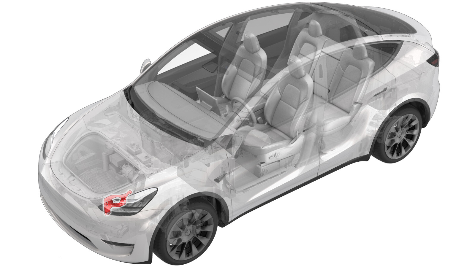
Bracket - Front End Module (FEM) - LH (Remove and Replace)
 Correction code
10101032
0.78
NOTE: Unless otherwise explicitly
stated in the procedure, the above correction code and FRT reflect all of the work
required to perform this procedure, including the linked procedures. Do not stack correction codes unless
explicitly told to do so.
NOTE: See Flat Rate
Times to learn more about FRTs and how they are created. To provide feedback on
FRT values, email ServiceManualFeedback@tesla.com.
NOTE: See Personal Protection to make sure wearing proper PPE when
performing the below procedure. See Ergonomic Precautions for safe and healthy working practices.
Torque Specifications
| Description | Torque Value | Recommended Tools | Reuse/Replace | Notes |
|---|---|---|---|---|
| Bolts that attach the LH front end module bracket to the vehicle |
 35 Nm (25.8 lbs-ft) |
|
Reuse | |
| Bolt that attaches the LH front fender bracket to the front fender assembly |
 9.8 Nm (7.2 lbs-ft) |
|
Reuse | |
| Bolt that attach the LH front end module braket to the front end carrier |
 16 Nm (11.8 lbs-ft) |
|
Reuse |
Remove
- Disconnect 12V power. See 12V/LV Power (Disconnect and Connect).
- Remove the front fascia. See Fascia - Front (Remove and Install).
-
Remove the LH front ride height sensor harness from the FEM bracket assembly.
Note2x clips
-
Disconnect the LH front ride height sensor connector.
Note1x connector
-
Disconnect the LH front wheel speed sensor connector.
Note1x clip, 1x connector, Release locking tab
-
Disconnect the LH FEM harness connector.
Note1x connector, Disengage locking tab
-
Disconnect the cooling fan module connector.
Note1x connector, Disconnect this after coolant hose is capped to avoid coolant damaging connector
-
Release the cooling fan module harness from the FEM bracket assembly.
Note1x clip
-
Disconnect the connectors from horn assembly.
Note2x connectors
-
Disconnect the LH headlamp connector.
Note1x connector, Pull tab to disengage lock mechanism, Pull again to release connector, Do not press down on tab
- Remove the LH impact accelerometer. See Sensor - Impact Accelerometer - Front Bumper - LH (Remove and Replace)
-
Release the clips that attach the FEM electrical harness to the front end carrier, and then remove the harness from the front end carrier.
Note1x clip
-
Remove the bolts (x3) that attach the front end module bracket assembly to the vehicle.
 35 Nm (25.8 lbs-ft)TIpUse of the following tool(s) is recommended:
- 13 mm socket
- Ratchet/torque wrench
-
Remove the bolt that attach the front end module bracket to the front fender assembly.
 9.8 Nm (7.2 lbs-ft)TIpUse of the following tool(s) is recommended:
- 10 mm deep socket
- 4 in extension
- Ratchet/torque wrench
-
Remove the bolt that attach the front end module bracket to the front end carrier.
 16 Nm (11.8 lbs-ft)TIpUse of the following tool(s) is recommended:
- 13 mm socket
- 6 in extension
- Flex head ratchet/flex head torque wrench
Install
-
Install the bolt that attach the front end module bracket to the front end carrier.
 16 Nm (11.8 lbs-ft)TIpUse of the following tool(s) is recommended:
- 13 mm socket
- 6 in extension
- Flex head ratchet/flex head torque wrench
-
Install the bolt that attach the front end module bracket to the front fender assembly.
 9.8 Nm (7.2 lbs-ft)TIpUse of the following tool(s) is recommended:
- 10 mm deep socket
- 4 in extension
- Ratchet/torque wrench
-
Remove the bolts (x3) that attach the front end module bracket assembly to the vehicle.
 35 Nm (25.8 lbs-ft)TIpUse of the following tool(s) is recommended:
- 13 mm socket
- Ratchet/torque wrench
-
Route the front harness through the LH FEM bracket assembly, and secure the front harness to the bracket.
Note1x clip
- Install the LH impact accelerometer. See Sensor - Impact Accelerometer - Front Bumper - LH (Remove and Replace)
-
Connect the LH headlamp connector.
Note1x connector, 1x locking tab
-
Connect the horn assembly connectors.
Note2x connectors
-
Connect the cooling fan module connectors and then install the clip.
Note1x clipNote1x connector
-
Connect the LH FEM harness connector.
Note1x connector, Engage locking tab
-
Connect the LH front ride height sensor connector and then install the clips.
Note2x clips, 1x connector
-
Connect the LF wheel speed sensor connector.
Note1x clip, 1x connector, Engage locking tab
- Install the front fascia. See Fascia - Front (Remove and Install).
- Connect 12V power. See 12V/LV Power (Disconnect and Connect).