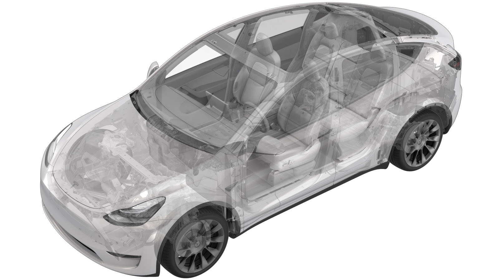
Controller - High Voltage (Structural Pack) (Remove and Replace)
 Correction code
16301632
1.86
NOTE: Unless otherwise explicitly
stated in the procedure, the above correction code and FRT reflect all of the work
required to perform this procedure, including the linked procedures. Do not stack correction codes unless
explicitly told to do so.
NOTE: See Flat Rate
Times to learn more about FRTs and how they are created. To provide feedback on
FRT values, email ServiceManualFeedback@tesla.com.
NOTE: See Personal Protection to make sure wearing proper PPE when
performing the below procedure. See Ergonomic Precautions for safe and healthy working practices.
- 2025-11-17: Added step to apply dielectric grease to the X484 connector. Added step to tuck the pyrotechnic disconnect harness underneath the ancillary bay harness.
- 2023-11-10: Added links for 3-phase structural pack ancillary bay cover procedure.
Remove
- Move the vehicle to a 2 post lift. See Raise Vehicle - 2 Post Lift.
- If the high voltage controller is being removed as part of another component's replacement procedure, and the same controller will be installed later, go to step 4. Otherwise, continue to the next step.
- Perform a backup of the high voltage controller data. See Controller - High Voltage (Backup and Restore).
- Remove the ancillary bay cover. See Cover - Ancillary Bay (Structural Pack) (Remove and Replace) or Cover - Ancillary Bay (Structural Pack) (3-Phase) (Remove and Replace).
- Remove the pyrotechnic battery disconnect. See Pyrotechnic Battery Disconnect (Structural Pack) (Remove and Install).
-
Disconnect the ancillary bay harness from
the high voltage controller connectors.
-
Remove the bolts (x2) that attach the
high voltage controller to the high voltage controller tray, and then remove the high
voltage controller from the vehicle.
Install
-
Position the high voltage controller tray on the high voltage controller, and then
install the bolts that attach the tray to the controller.
 2 Nm (1.5 lbs-ft)NoteCheck the correct REV- for the HVC before installation, and make sure the REV- is compatible with the old HVC.
 -
Apply dielectric grease to the X484
connector cavity.
CAUTIONUse a syringe if possible and do not bend the connector pins.
Figure 1. X484 Connector -
Connect the ancillary bay harness to the
high voltage controller connectors.
NoteWipe off any excess grease after inserting the X484 connector.
- Install the pyrotechnic battery disconnect. See Pyrotechnic Battery Disconnect (Structural Pack) (Remove and Install).
-
Tuck the pyrotechnic disconnect wiring
under the main ancillary bay harness.
- If the high voltage controller was removed and then installed as part of another component's replacement procedure, return to that procedure.
- Inspect the inner edge of the vehicle single-piece rear casting for metal flashing. If flashing is present, put on cut-resistant gloves.
-
Inspect the ancillary bay phantom seal and
verify that no damage is present. Otherwise, replace the seal.
-
With the help of an assistant,
position the LH side of the ancillary bay cover over the DC input HV header, pivot the cover
to under the body casting, position the RH side of the cover over the high voltage
controller connector and DC output connector, and then lower the cover onto the
ancillary bay.
-
Install the two bolts on either side
of the high voltage controller connector.
 10 Nm (7.4 lbs-ft)
 -
Connect the electrical harness to the high voltage controller connector.
- Connect LV power. See 12V/LV Power (Disconnect and Connect).
-
Connect an LV maintainer. See LV Maintainer (Connect and Disconnect).
- Perform a restore of the high voltage controller data. See Controller - High Voltage (Backup and Restore).
- Disconnect the LV maintainer. See LV Maintainer (Connect and Disconnect).
- Install the ancillary bay cover. See Cover - Ancillary Bay (Structural Pack) (Remove and Replace) or Cover - Ancillary Bay (Structural Pack) (3-Phase) (Remove and Replace).
- Disable Service Mode from the touchscreen. See Service Mode.
- Remove the vehicle from the 2 post lift. See Raise Vehicle - 2 Post Lift.