Suspension - Front (Check Torque)
Correction code 31019000 0.60 NOTE: Unless otherwise explicitly stated in the procedure, the above correction code and FRT reflect all of the work required to perform this procedure, including the linked procedures. Do not stack correction codes unless explicitly told to do so. NOTE: See Flat Rate Times to learn more about FRTs and how they are created. NOTE: See Personal Protection to make sure wearing proper PPE when performing the below procedure. NOTE: See Ergonomic Precautions for safe and healthy working practices.
Procedure
- Remove the LH and RH front wheels. See Wheel Assembly (Remove and Install).
- Remove the front aero shield panel. See Panel - Aero Shield - Front (Non-Structural Pack) (Remove and Replace).
-
Remove the clips (x2) that attach the valance to the front stabilizer bar brackets.
-
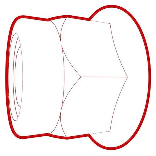
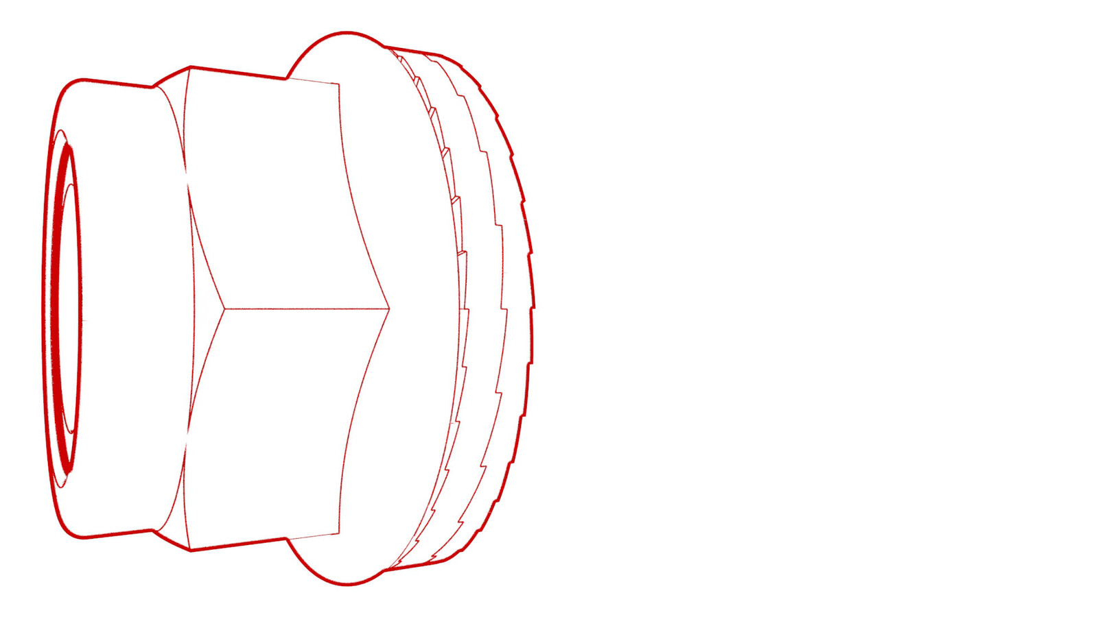
Check the torque for the nuts that attach the front stabilizer bar to the front subframe, and then mark the nuts with a paint pen.
 35 Nm (25.8 lbs-ft)
 -
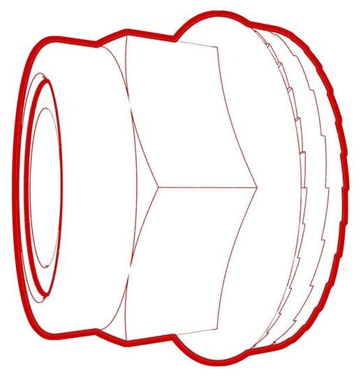
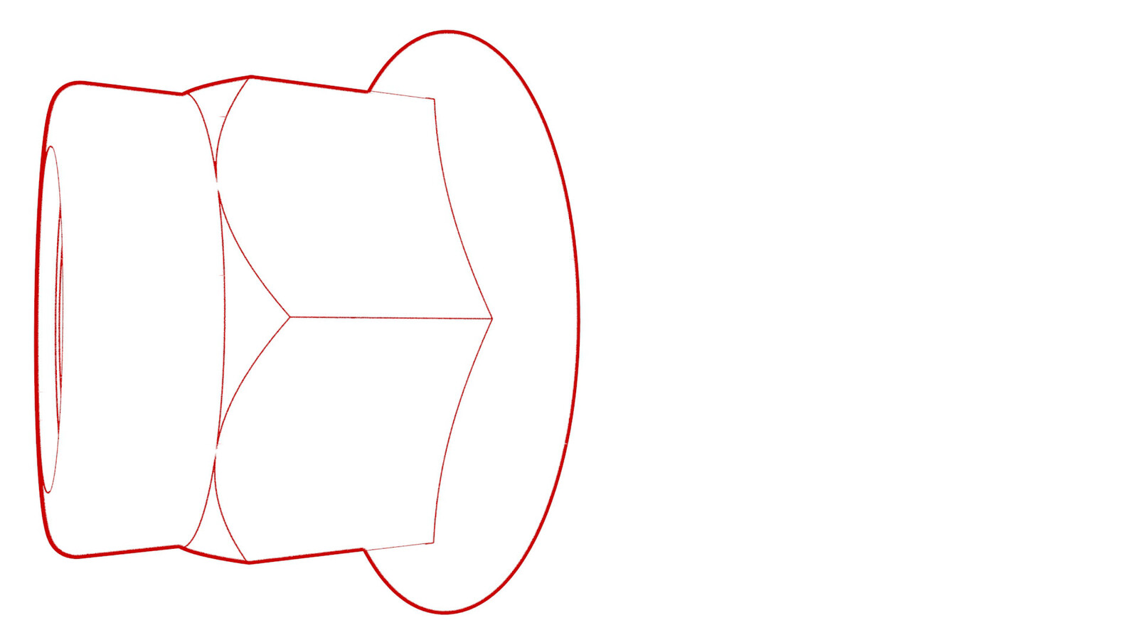
Check the torque for the nut that attaches the LH front stabilizer bar link to the LH front spring and damper assembly, and then mark the nut with a paint pen.
 98 Nm (72.3 lbs-ft)
 -
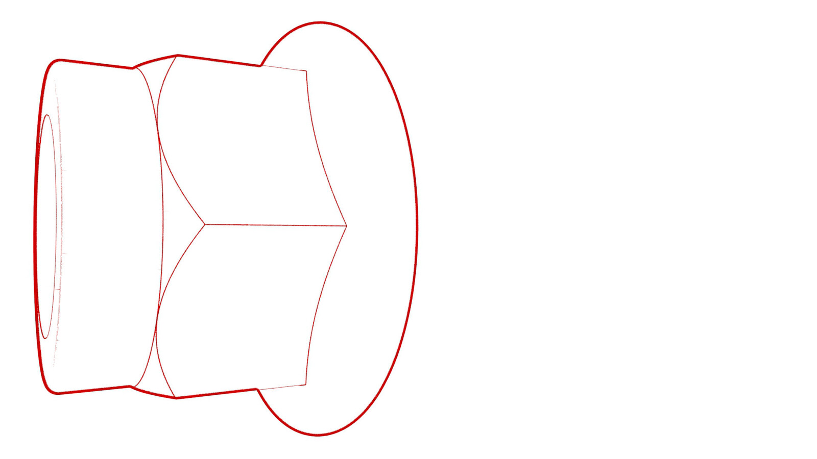
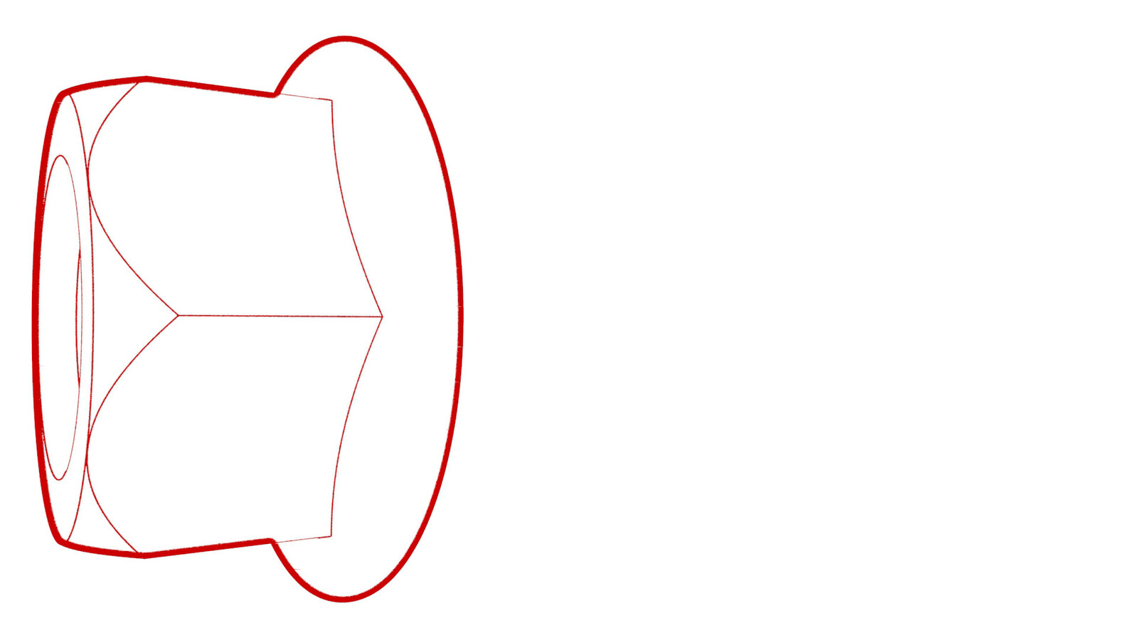
Check the torque for the nut that attaches the LH tie rod end to the LH knuckle, and then mark the nut with a paint pen.
 180 Nm (132.7 lbs-ft)
 -
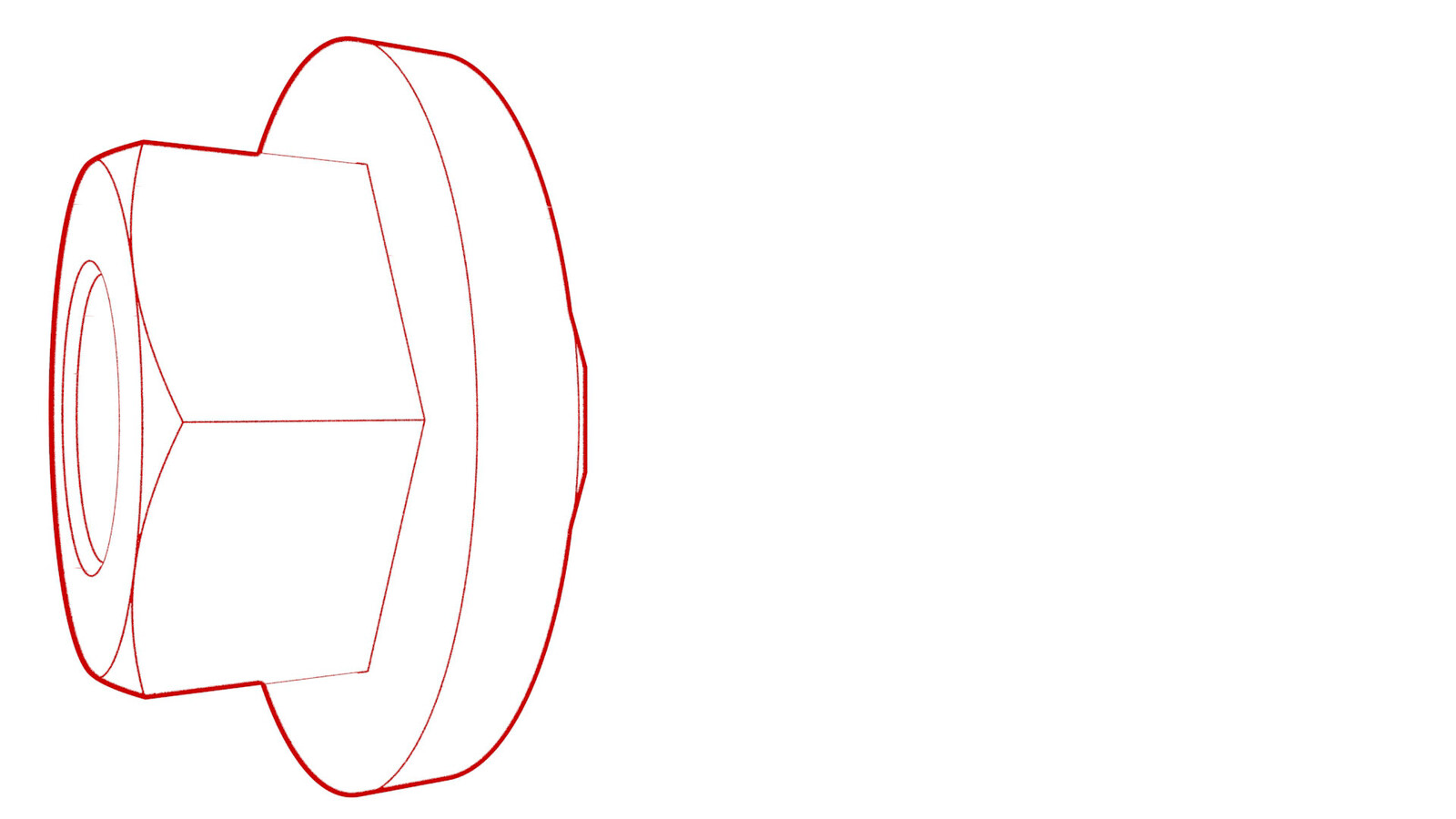
Check the torque for the nut that attaches the LH upper control arm to the LH knuckle, and then mark the nut with a paint pen.
 56 Nm (41.3 lbs-ft)
 -
Check the torque for the nut
that attaches the LH front lower compliance link to the front subframe, and
then mark the nut with a paint pen.
 115 Nm (84.8 lbs-ft)
 -
Check the torque for the
nuts that attach the LH front lower lateral link to the front subframe, and
then mark the nuts with a paint pen.
Torque specification for 2123635-00-ATorque specification for 1109912-00-B190 Nm (140.1 lbs-ft)135 Nm (99.6 lbs-ft)NoteThere are two types of bolts that are difficult to distinguish visually, each requiring different torque values.
- 2123635-00-A (Currently only available in EMEA and APAC): 190 Nm
- 1109912-00-B (NA, use only): 135 Nm
Refer to article 27022 to confirm the residue torque and set the torque value in the digital torque wrench to 115Nm:
- If the bolt rotation is less than 180 degrees, retighten to 135 Nm;
- Otherwise replace the bolts and tighten them to the standard torque value listed in the Link - Lateral - Lower - Front - LH (Remove and Replace).
-
Check the torque for the nut that attaches the LH front lower compliance link to the LH knuckle, and then mark the nut with a paint pen.
 180 Nm (132.7 lbs-ft)
 -
Check the torque for the nut that attaches the LH front lower lateral link to the LH knuckle, and then mark the nut with a paint pen.
 180 Nm (132.7 lbs-ft)
 -
Check the torque for the nut that attaches the LH front stabilizer bar link to the front stabilizer bar, and then mark the nut with a paint pen.
 98 Nm (72.3 lbs-ft)
 - Repeat step 5 through step 12 on the RH side of the front suspension.
- Install the LH and RH front wheels. See Wheel Assembly (Remove and Install).
- Raise the vehicle on a 4 post lift. See Raise Vehicle - 4 Post Lift.
-
Check the torque for the nut that attaches the LH front spring and damper assembly to the LH front lower lateral link, and then mark the nut with a paint pen.
 106 Nm (78.2 lbs-ft)
 -
Check the torque for the nut that attaches the RH front spring and damper assembly to the RH front lower lateral link, and then mark the nut with a paint pen.106 Nm (78.2 lbs-ft)
-
Install the clips (x2) that attach the valance to the front stabilizer bar brackets.
- Install the front aero shield panel. See Panel - Aero Shield - Front (Non-Structural Pack) (Remove and Replace).
- Remove the vehicle from the 4 post lift. See Raise Vehicle - 4 Post Lift.