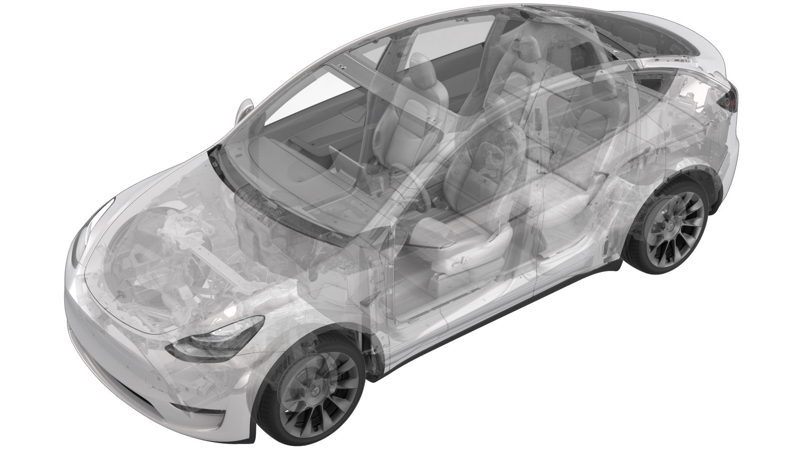
Ball Joint - Rear - Upper - Rear Knuckle - LH (Remove and Replace)
 Correction code
31031812
0.48
NOTE: Unless
otherwise explicitly stated in the procedure, the above correction code and
FRT reflect all of the work required to perform this procedure, including
the linked procedures. Do
not stack correction codes unless explicitly told to do so.
NOTE: See Flat Rate
Times to learn more about FRTs and how
they are created. To provide feedback on FRT values, email ServiceManualFeedback@tesla.com.
NOTE: See Personal Protection
to make sure wearing proper PPE when performing the below procedure.
NOTE: See Ergonomic Precautions for safe and
healthy working practices.
- 2025-12-9: Added information for updated tools.
- 2025-10-09: Added caution for tool usage.
- 2025-08-13: Added part numbers for required chemicals.
- 2025-06-04: Added references to sub-procedures.
- 2025-02-20: Added note to use region specific Loctite.
Equipment:
- 1044454-00-B - RR SUS CABJ
- 2130203-00-A or 2130203-00-B - CABJ Bushings R&R Tool Kit M3/MY
- 1025334-00-A - Loctite 680 (North America)
- 2164041-00-A - Loctite 638 (EMEA)
- Remove the LH rear wheel. See Wheel Assembly (Remove and Install)
-
Inspect LH Rear Upper Knuckle Ball Joint
for red markings.
NoteThe Knuckle Ball Joint is a 1 time replaceable part. If the red markings are present on opposite sides (180 degrees), the Knuckle Ball Joint has already been replaced. Replace the entire knuckle assembly instead. See Knuckle - Suspension - Rear - LH (Remove and Replace).
-
Release LH rear upper aft link from
knuckle
Note1x bolt, 1x nut, 21mm, 134 Nm
-
Remove the Rear Upper Knuckle Ball joint using revision 2130203-00-A of the CABJ
Bushings R&R Tool Kit M3/MY.
NoteGo to the next step when using revision 2130203-00-B.
-
Remove the Rear Upper Knuckle Ball joint using revision 2130203-00-B of the CABJ
Bushings R&R Tool Kit M3/MY.
- Put on protection gloves
-
Clean LH Rear knuckle
NoteClean surface area where Rear Upper Knuckle Ball Joint is installed into the knuckle from any debris and oxidation, allow 1 minute dry time
-
Degrease LH Rear Upper Knuckle Ball
Joint
NoteClean contact area of Rear Upper Knuckle Ball Joint and allow 1 minute dry time
-
Apply Loctite on LH Rear Upper Knuckle
Ball Joint
NoteUse the region specific Loctite. For EMEA: Loctite 638. For North America: Loctite 680NoteTake care not to apply loctite on the rubber sealsCAUTIONAllow 30 minutes curing time for Loctite. Continue this procedure, but do not drive the vehicle during the 30 minute curing time.
-
Position new LH Rear Upper Knuckle Ball
Joint to knuckle
NoteEnsure ball joint is sitting concentric to the bore, installation is performed from the rear side of the knuckle and ball joint has only 1 orientation of the installation, discard Nitrile Gloves
-
Install the Rear Upper Knuckle Ball joint using revision 2130203-00-A of the CABJ
Bushings R&R Tool Kit M3/MY.
NoteGo to the next step when using revision 2130203-00-B.
-
Install the Rear Upper Knuckle Ball joint using revision 2130203-00-B of the CABJ
Bushings R&R Tool Kit M3/MY.
-
Clean any excessive Loctite from LH Rear
Upper Knuckle
NoteAllow 1 minute dry time
-
Mark the LH Rear Upper Knuckle Ball
Joint with red paint pen.
NoteMachined surface should be near flush with ball joint. Markings must be on opposite sides (180 degrees).
-
Position LH rear upper aft link to
knuckle
Note1x bolt, 1x nut, 21mm, 134 Nm, Torque at later step
-
Torque bolt securing LH rear upper aft
link to knuckle
Note1x bolt, 21mm, 134 Nm, Mark with paint pen
- Install the LH rear wheel. See Wheel Assembly (Remove and Install)
- Refer to the Alignment Requirement tables to determine whether an EPAS alignment check (EC) or four wheel alignment check (AC) is necessary. If performed, add the alignment check/adjust correction code as a separate activity to the SV. See Alignment Requirement - Suspension.